
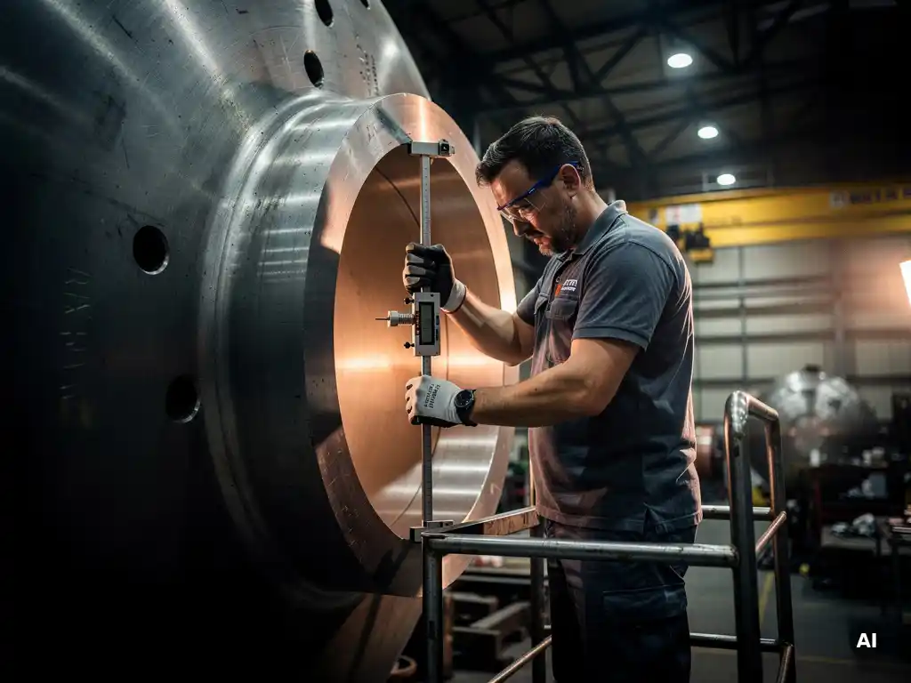
High-pressure reactor vessels require dimensional tolerances that are tighter than those for standard pressure equipment, because even small deviations in geometry can affect structural integrity, sealing performance, and internal process conditions. The exact tolerances depend on the vessel’s design pressure, wall thickness, material, and applicable code, but fabricators working to ASME or PED requirements must meet defined limits for shell roundness, wall thickness, nozzle placement, and flange facing. The sections below work through the most important tolerance questions that engineers and procurement teams encounter when specifying or sourcing reactor vessels.
Which dimensions in a reactor vessel are most tolerance-critical?
The most tolerance-critical dimensions in a reactor vessel are shell roundness (out-of-roundness), wall thickness, nozzle orientation and elevation, flange facing flatness, and the alignment of internal components such as trays, baffles, or agitator supports. These dimensions directly affect pressure-bearing capacity, sealing integrity, and the correct functioning of internals under operating conditions.
Out-of-roundness in the shell is particularly consequential in high-pressure applications. A shell that deviates from a true circle develops uneven stress distribution under internal pressure, which can accelerate fatigue or cause localized yielding. Nozzle placement is equally critical when the vessel connects to external piping under load, or when internal components must align precisely with process flow paths. Flange facing tolerances determine whether a bolted joint can achieve the required seating stress across the entire gasket surface, which is fundamental to leak-tight performance in demanding service.
How do wall thickness and pressure rating affect tolerance requirements?
Higher pressure ratings demand thicker walls, and thicker walls make dimensional tolerances both more critical and more difficult to achieve. As wall thickness increases, the consequences of thickness under-tolerance become more severe, because the design margin is calculated on the minimum acceptable wall. A vessel operating at high pressure with a wall that falls below the minimum required thickness is operating outside its design basis.
Fabrication codes set minimum wall thickness as a hard lower limit, not a target. This means the nominal ordered plate thickness must account for the manufacturer’s mill tolerance on the incoming material, the material removed during any machining or weld preparation, and any thinning that occurs during forming. For thick-walled reactor vessels, this calculation must be carried out carefully to ensure the finished wall thickness remains above the code minimum across the entire shell, including formed heads where thinning during pressing is predictable but must be controlled.
The relationship between pressure rating and tolerance is also relevant to nozzle reinforcement areas, where the local geometry must compensate for the material removed by the opening. Inaccuracies in the reinforcement zone dimensions can result in a nozzle that does not meet the required area replacement calculations.
What do ASME and PED codes actually specify for dimensional tolerances?
ASME Section VIII Division 1 and Division 2 specify permissible out-of-roundness as a percentage of the nominal inside diameter, with tighter limits applying to vessels designed under Division 2. PED (Pressure Equipment Directive) does not itself prescribe specific dimensional tolerances but requires that the design and fabrication meet the essential safety requirements, which in practice means compliance with harmonized standards such as EN 13445. Both frameworks set minimum wall thickness as a lower bound with no permissible negative deviation in the finished vessel.
Under ASME VIII Division 1, the maximum difference between the largest and smallest inside diameter at any cross-section is limited to 1% of the nominal diameter for vessels not subject to external pressure. Division 2 applies more stringent roundness requirements, particularly for vessels where buckling under external pressure is a design consideration. EN 13445 similarly specifies roundness tolerances that tighten as the ratio of shell diameter to wall thickness changes.
Nozzle location tolerances under ASME are typically expressed as angular and linear deviations from the drawing position. Flange facing tolerances cover flatness and the permissible angle of the flange face relative to the pipe axis. These are not left to fabricator discretion; they are defined in the applicable code or referenced standard and verified during inspection.
Why do advanced materials make dimensional tolerances harder to hold?
Advanced materials such as titanium, zirconium, Hastelloy, and Inconel behave differently from carbon steel during forming, welding, and heat treatment, and these differences make dimensional tolerances harder to control. Springback during cold forming is more pronounced in some alloys, weld shrinkage and distortion patterns differ from those in carbon steel, and certain materials require post-weld heat treatment that can introduce additional dimensional change.
Titanium, for example, has a lower modulus of elasticity than carbon steel, which means it springs back more after cold forming. Achieving the required shell roundness in titanium therefore requires either tighter control during forming or additional correction steps. Nickel alloys such as Inconel and Hastelloy are significantly stronger than carbon steel at elevated temperatures, which affects the force required during hot forming and the behavior of the material as it cools.
Clad constructions introduce a further complication. A vessel built with a carbon steel shell and a corrosion-resistant inner layer of a different alloy must be formed and welded in a way that keeps both layers within tolerance while managing the differential thermal expansion and contraction between them. The cladding must maintain full bond integrity and consistent thickness across the finished shell, which adds inspection requirements beyond those for solid-material construction.
How are dimensional tolerances verified during and after fabrication?
Dimensional tolerances in reactor vessels are verified through a combination of in-process dimensional checks and final inspection measurements, using calibrated instruments traceable to recognized standards. Key measurements include shell diameter at multiple cross-sections, wall thickness using ultrasonic testing, nozzle position and orientation, flange facing flatness, and the alignment of any internal structural components.
In-process verification is more effective than end-of-fabrication inspection alone, because many dimensions become inaccessible once subsequent fabrication stages are complete. Shell roundness, for instance, should be checked after each major forming and welding stage, not only at the end. Weld shrinkage is predictable to a degree, but its actual effect on the finished geometry must be confirmed by measurement rather than assumed.
For critical reactor vessels, the inspection plan is typically agreed between the fabricator, the client, and any third-party inspection authority before fabrication begins. Hold points, where work cannot proceed until a dimensional check has been signed off, are incorporated into the fabrication sequence at stages where deviations can still be corrected. Final dimensional records form part of the vessel documentation package and are required for code compliance.
What happens when a reactor vessel fails to meet its dimensional tolerances?
When a reactor vessel does not meet its specified dimensional tolerances, the fabricator must either correct the deviation or demonstrate through engineering analysis that the as-built condition remains acceptable. Correction options depend on the nature and magnitude of the deviation. Minor out-of-roundness may be correctable by re-rolling or mechanical intervention; nozzle misalignment may require weld repair and repositioning. Deviations that cannot be corrected must be formally assessed.
A formal fitness-for-service or concession assessment evaluates whether the deviation affects the vessel’s structural integrity or its ability to function within the process requirements. This assessment must be accepted by the responsible engineer and, in many cases, by the third-party inspection authority. If the deviation is accepted as-built, it is documented and forms part of the permanent vessel record. If it is not acceptable and cannot be corrected, the affected component must be rejected and remade.
The commercial and schedule consequences of dimensional non-conformance in a large reactor vessel are significant. Rework on thick-walled or clad components is time-consuming and technically demanding. In some cases, a non-conforming shell course or head must be scrapped entirely. This is one of the strongest arguments for rigorous in-process dimensional control rather than relying on end-of-fabrication inspection to catch problems.
How Coek supports dimensional accuracy in high-pressure reactor vessel fabrication
Coek Engineering manufactures custom reactor vessels and industrial autoclaves for demanding applications where dimensional accuracy is non-negotiable. Our approach to tolerance management covers the full fabrication sequence, from material selection and forming through welding, heat treatment, and final inspection.
- In-house mechanical engineering to translate process requirements into dimensionally compliant designs
- Experience with advanced and exotic materials including titanium, zirconium, Hastelloy, Inconel, and clad constructions
- Fabrication of large, thick-walled vessels where dimensional control is most challenging
- Structured inspection planning with defined hold points aligned to ASME and PED requirements
- Complete dimensional documentation as part of the vessel certification package
If you are specifying or sourcing a high-pressure reactor vessel with demanding dimensional requirements, contact Coek Engineering to discuss your project with our engineering team.
Frequently Asked Questions
How do I determine which tolerance standard — ASME Division 1 vs. Division 2 — is more appropriate for my reactor vessel project?
The choice between ASME VIII Division 1 and Division 2 typically comes down to operating pressure, wall thickness, and the level of design scrutiny your application demands. Division 2 is generally more appropriate for higher-pressure vessels where tighter roundness tolerances and more rigorous stress analysis provide a meaningful safety and efficiency benefit — often allowing thinner walls for the same pressure rating. If you are unsure which division applies, your engineering team or fabricator should review your design pressure, material, and service conditions against the applicability criteria in each division before the design basis is fixed.
What are the most common dimensional tolerance mistakes made during the specification phase, and how can I avoid them?
One of the most frequent mistakes is specifying nominal wall thickness without accounting for mill undertolerance on incoming plate, material removed during weld preparation, and thinning during head forming — leaving the finished vessel below the code minimum. Another common error is placing tight nozzle position tolerances on the drawing without coordinating them with the connected piping layout, which can create impossible-to-meet requirements that only surface during final fit-up. To avoid these issues, involve your fabricator early in the design phase so that achievable tolerances are agreed upon before the drawing is issued for fabrication.
Can dimensional tolerances be relaxed if my reactor vessel operates at lower pressures or temperatures?
While lower operating pressures reduce some of the structural consequences of dimensional deviation, code-mandated tolerances such as minimum wall thickness and out-of-roundness limits still apply regardless of operating pressure, because they are set as baseline fabrication quality requirements. That said, the engineering significance of a given deviation — for example, a minor nozzle misalignment — may be easier to justify through a fitness-for-service assessment in a lower-pressure application. Any formal relaxation of a specified tolerance must still be documented, assessed by a responsible engineer, and accepted by the relevant inspection authority.
How does post-weld heat treatment (PWHT) affect the dimensional tolerances achieved during fabrication?
PWHT can introduce measurable dimensional changes, particularly in large or complex assemblies, because the thermal cycle causes localized expansion and contraction that may alter shell roundness, nozzle orientation, or flange face alignment. For thick-walled vessels or those made from materials with significant thermal sensitivity — such as nickel alloys — the dimensional impact of PWHT should be anticipated and, where possible, factored into pre-PWHT geometry targets. A final dimensional inspection after PWHT is essential, as dimensions accepted before heat treatment cannot be assumed to remain within tolerance afterward.
What documentation should I expect to receive from a fabricator confirming that dimensional tolerances have been met?
A compliant fabricator should provide a full dimensional inspection report as part of the vessel’s documentation package, covering all critical dimensions verified against the drawing and the applicable code — including shell diameter measurements at multiple cross-sections, wall thickness readings, nozzle positions and orientations, and flange facing flatness. This report should reference the calibrated instruments used, be signed off by a qualified inspector, and include any concession or deviation records for dimensions that were formally assessed rather than corrected. Under ASME and PED frameworks, this documentation is not optional — it forms part of the certification record required for the vessel to be legally placed into service.
How does the size of a reactor vessel affect the difficulty of holding dimensional tolerances?
Larger vessels are inherently more challenging to fabricate within tight tolerances because small angular or positional errors accumulate over greater distances, weld shrinkage effects are multiplied across longer seam lengths, and the sheer weight of components makes precise positioning and re-correction more demanding. Nozzle elevation tolerances that are straightforward to achieve on a 1-meter-diameter vessel can require significantly more care on a vessel with a 4-meter shell. Fabricators experienced with large reactor vessels will account for these scale effects in their welding sequences, forming procedures, and inspection hold point planning.
At what stage of a project should dimensional tolerances be discussed with a potential fabricator?
Dimensional tolerances should be discussed with your fabricator during the enquiry or early engineering phase — well before drawings are finalized and certainly before any material is ordered. This conversation allows the fabricator to flag any tolerance requirements that are unusually tight for the material or geometry involved, confirm that their equipment and processes can reliably achieve the specified limits, and advise on how nominal dimensions should be set to ensure the finished vessel meets code minimums after all fabrication steps. Raising these questions late in the process, or only at the inspection stage, significantly increases the risk of costly non-conformances.
Related Articles
- What are the main manufacturing challenges of large shell-and-tube heat exchangers?
- What are the most common pressure vessel failures and their causes?
- What non-destructive testing methods apply to thick-walled pressure equipment?
- What is an industrial autoclave used for?
- What is a large capacity autoclave?