
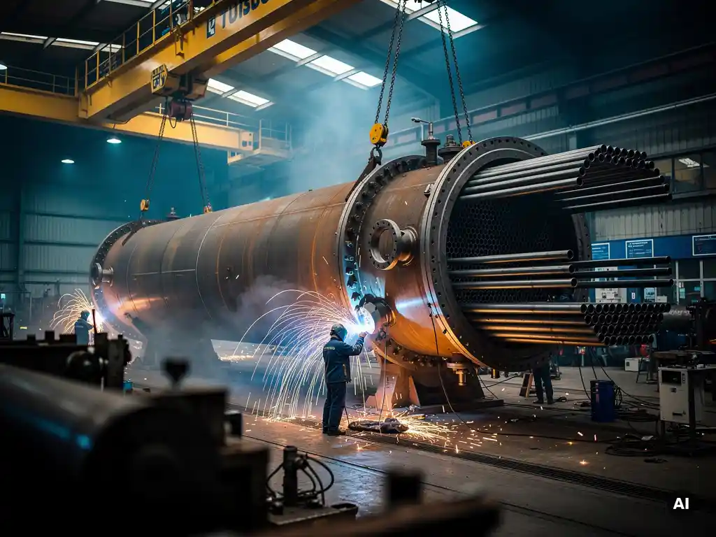
The main manufacturing challenges of large shell-and-tube heat exchangers include controlling dimensional tolerances across long shells, achieving reliable tube-to-tubesheet joints, managing thermal distortion during welding, and working with exotic or clad materials that require specialised fabrication techniques. These challenges intensify as equipment grows in size, operating pressure, or material complexity. The questions below unpack each challenge in detail.
Why do large shell-and-tube heat exchangers fail during fabrication?
Large shell-and-tube heat exchangers most commonly fail during fabrication due to weld defects at tube-to-tubesheet joints, uncontrolled thermal distortion in the shell, and inadequate dimensional control over long lengths. These failures are rarely isolated events: they typically result from a combination of material sensitivity, joint complexity, and the cumulative effect of fabrication steps that each introduce small deviations.
As shell diameter and length increase, the number of welds and mechanical joints multiplies. Each weld introduces heat input, which causes local expansion and contraction. Without precise sequencing and inter-pass temperature control, residual stresses accumulate and can cause cracking, distortion, or leak paths that only become apparent during pressure testing.
Material selection adds another layer of risk. Exotic alloys such as titanium, zirconium, and Hastelloy respond differently to heat than carbon steel. They have narrower acceptable welding windows, are more sensitive to contamination, and can crack or lose corrosion resistance if fabrication parameters drift outside specification. In clad constructions, the bond between the base material and the corrosion-resistant layer must remain intact throughout all forming, welding, and heat treatment operations.
Fabrication failure is therefore not a single-point problem. It is the result of inadequate process control across multiple interdependent steps, each of which must be managed with documented procedures and qualified personnel.
How do shell diameter and length affect manufacturability?
Shell diameter and length directly affect manufacturability by determining the forming forces required, the number of welded joints needed, the complexity of internal assembly, and the logistical demands of handling and transport. As either dimension increases, the margin for error in every fabrication step narrows.
Larger diameters require heavier plate rolling equipment capable of maintaining consistent curvature without springback or ovality. A shell that is out-of-round will create alignment problems when fitting tubesheets, flanges, and nozzles. In heat exchangers where tube bundles must slide in and out for maintenance, even small deviations in shell roundness can prevent bundle insertion or cause localised contact stress.
Greater length introduces challenges around straightness and weld joint alignment. Each shell course must be aligned precisely before welding, and any angular deviation compounds over the full length of the vessel. For very long exchangers, this requires purpose-built rollers and alignment tooling, as well as careful control of welding sequence to prevent the shell from bowing.
Transport constraints also shape manufacturability. Exchangers that exceed road transport limits in diameter or length must either be fabricated in sections and field-assembled (which introduces its own quality challenges) or manufactured at a facility with direct access to heavy-lift logistics. Production facilities with sufficient indoor floor space and crane capacity to handle large assemblies in a controlled environment are essential for maintaining quality on oversized equipment.
What are the main challenges of tube-to-tubesheet joint integrity?
Tube-to-tubesheet joint integrity is one of the most critical and technically demanding aspects of shell-and-tube heat exchanger fabrication. The joint must seal reliably under operating pressure and temperature cycling while resisting corrosion on both the shell side and the tube side. Achieving this consistently across hundreds or thousands of joints in a single exchanger requires tight control of expansion, welding, and inspection procedures.
There are two primary joint types: expanded joints, where the tube is mechanically deformed outward into the tubesheet bore, and welded joints, where a fillet or full-penetration weld is added. Many demanding applications require both. The challenge with expansion is achieving uniform contact pressure without over-expanding, which can thin the tube wall and reduce its fatigue life. Under-expansion leaves gaps that allow crevice corrosion or leak paths under thermal cycling.
Welded tube-to-tubesheet joints introduce additional complexity when exotic materials are involved. Titanium tubes welded to titanium or titanium-clad tubesheets require inert gas shielding on both sides of the weld to prevent oxidation and embrittlement. Zirconium is even more sensitive. Any contamination during welding can compromise the corrosion resistance of the joint, which is typically exposed to the most aggressive operating environment in the exchanger.
For applications such as PTA production, where high-pressure preheaters operate at elevated temperatures with titanium Grade 9 tubes, the expansion step itself must be carefully engineered. Ti Grade 9 has lower elongation than Grade 2, which means standard expansion procedures can cause cracking. Fabricators with experience in this material develop dedicated procedures that balance the mechanical requirements of the joint against the metallurgical limits of the alloy.
Which materials make shell-and-tube heat exchanger fabrication more difficult?
Exotic and high-performance alloys significantly increase fabrication difficulty compared to carbon or stainless steel. The materials that present the greatest challenges are titanium grades, zirconium, tantalum, and nickel-based alloys such as Hastelloy C-276. Each requires specialised welding procedures, dedicated tooling, and strict contamination controls that standard fabrication shops are not equipped to provide.
Key material-specific challenges include:
- Titanium: Highly reactive at elevated temperatures, requiring full inert gas shielding during welding. Different grades (Grade 2, Grade 9, Grade 17) have distinct mechanical properties that affect forming, expansion, and welding parameters. Ti Grade 9, used in high-pressure preheaters for PTA applications, has lower elongation than softer grades, making tube expansion particularly demanding.
- Zirconium: Extremely sensitive to oxygen, nitrogen, and hydrogen contamination during welding. Requires dedicated welding chambers or trailing shields and highly qualified welders. Used in applications involving acetic acid, brine purification, and MEG production where other materials would corrode rapidly.
- Hastelloy C-276 and similar nickel alloys: Prone to sensitisation and hot cracking if inter-pass temperatures are not tightly controlled. Require low heat input welding techniques and careful post-weld handling. Used in biofuels and other chemically aggressive environments.
- Clad materials: Combinations of carbon steel with a corrosion-resistant inner layer (titanium, zirconium, or Hastelloy) require that all fabrication steps preserve the metallurgical bond. Forming, cutting, and welding must be sequenced to avoid delamination or disbonding at the interface.
The common thread across all these materials is that standard fabrication procedures do not apply. Each requires documented welding procedure specifications, qualified welders, dedicated equipment, and inspection methods appropriate to the material’s properties.
How are dimensional tolerances controlled in large heat exchanger shells?
Dimensional tolerances in large shell-and-tube heat exchangers are controlled through a combination of precision forming equipment, structured welding sequences, in-process measurement, and post-weld corrections. For long or large-diameter shells, tolerance control is an active process throughout fabrication, not a final check at the end.
Shell roundness is established during plate rolling and must be verified at each shell course before assembly. Ovality tolerances are specified by design codes such as ASME and TEMA, and deviations beyond these limits affect both the structural integrity of the shell and the fit-up of internal components. Purpose-built rolling equipment with calibrated pressure settings is needed to achieve consistent curvature in heavy plate.
Longitudinal straightness is controlled primarily through welding sequence. Welding one side of a seam before the other introduces asymmetric shrinkage, which causes the shell to bow. Experienced fabricators use balanced welding sequences, back-step techniques, and controlled heat input to minimise distortion. Straightness is measured continuously during assembly, and corrections are applied before the next course is added rather than attempting to correct a fully assembled shell.
Nozzle and flange orientation is another critical tolerance requirement. In shell-and-tube heat exchangers with multiple nozzles, the angular position and projection of each nozzle must fall within tight limits to allow piping connections in the field. Jigs, fixtures, and laser measurement tools are used to position nozzles accurately before welding, and final dimensions are verified against the certified drawings before the exchanger leaves the shop.
For very large or heavy exchangers, the weight of the shell itself can cause deflection during fabrication if support is not correctly distributed. Fabrication saddles and turning rolls must be positioned to avoid introducing bending loads that would distort the shell under its own weight.
What testing and inspection requirements apply to large shell-and-tube exchangers?
Large shell-and-tube heat exchangers are subject to a range of non-destructive examination, pressure testing, and documentation requirements defined by applicable design codes and the specific process conditions of the application. The scope of inspection increases with operating pressure, temperature, hazard classification, and material sensitivity.
Standard inspection activities typically include:
- Visual and dimensional inspection: Verification of all critical dimensions, nozzle orientations, surface finish, and weld appearance against certified drawings and applicable code requirements throughout fabrication.
- Non-destructive examination of welds: Radiographic testing (RT) or ultrasonic testing (UT) of shell seams and nozzle welds, with extent determined by the design code, material group, and pressure class. Magnetic particle or liquid penetrant testing is applied to detect surface-breaking defects, particularly in exotic alloys where visual inspection alone is insufficient.
- Tube-to-tubesheet joint examination: Helium leak testing, hydraulic testing, or eddy current inspection of tube-to-tubesheet joints, depending on the criticality of the application and the consequences of leakage between the shell side and tube side.
- Hydrostatic pressure test: The completed exchanger is pressurised with water to a test pressure defined by the applicable code (typically 1.25 to 1.5 times the design pressure) and held for a defined period while all joints and connections are inspected for leaks or deformation.
- Material traceability and documentation: Full material traceability from mill certificates through to the finished equipment, including welding procedure qualifications, welder qualifications, heat treatment records, and inspection reports compiled in a final data book.
For equipment certified under the European Pressure Equipment Directive (PED), ASME, or other recognised codes, a notified body or authorised inspector is involved at defined hold points during fabrication. The design team’s calculations, including supplementary analyses such as finite element analysis or thermal analysis where required, form part of the documented technical file that accompanies the equipment.
How Coek approaches shell-and-tube heat exchanger fabrication
Coek Engineering applies these principles across its full range of shell-and-tube heat exchangers for demanding industrial applications. The challenges described above, exotic materials, large dimensions, tight tolerances, and complex joint requirements, are precisely the conditions in which Coek’s fabrication capabilities are most relevant.
Key aspects of Coek’s approach include:
- Dedicated material specifications for demanding alloys, including a proven procedure for Ti Grade 9 tube expansion developed over more than 35 years of PTA fabrication experience
- In-house mechanical engineering that translates customer process requirements into manufacturable equipment, covering code calculations, FEA, thermal analysis, and vibration analysis
- Two production facilities in Belgium with a combined indoor floor area exceeding 35,000 square metres, capable of handling exchangers up to 10 metres in diameter and 100 metres in length
- Compliance with ASME, TEMA, PED, and AD Merkblätter, with full material traceability and documented inspection throughout fabrication
- Proven experience with clad construction, solid titanium, zirconium, Hastelloy, and other high-performance alloys across a range of demanding process applications
If your project involves a shell-and-tube heat exchanger where standard fabrication is insufficient, contact Coek Engineering to discuss your technical requirements.
Frequently Asked Questions
How do I know whether my application requires expanded, welded, or combination tube-to-tubesheet joints?
The choice depends on your operating pressure, temperature cycling severity, fluid hazard classification, and the consequences of leakage between the shell side and tube side. Welded joints are generally required when the process fluid is toxic, flammable, or extremely high-pressure, while expanded-only joints may be acceptable for lower-risk duties. Combination joints — expanded and welded — are specified when both mechanical strength and leak-tightness are critical, as is common in PTA preheaters and other high-pressure, high-temperature applications. A fabricator experienced in your specific process conditions and applicable design code (ASME, TEMA, PED) should review your duty specification before the joint type is finalised.
What are the most common mistakes made when specifying a large shell-and-tube heat exchanger for fabrication?
The most frequent mistakes include under-specifying material requirements (for example, listing a titanium grade without accounting for the mechanical differences between Grade 2 and Grade 9), setting tolerance requirements that are inconsistent with the selected design code, and failing to consider transport and installation constraints early in the design phase. Another common oversight is not aligning inspection hold points and documentation requirements with the applicable regulatory framework — particularly for PED-certified equipment — which can cause significant delays if raised late in fabrication. Engaging the fabricator during the engineering phase, rather than after detailed design is complete, helps catch these issues before they become costly.
Can a shell-and-tube heat exchanger be fabricated in sections and field-assembled without compromising quality?
Yes, but field assembly introduces quality challenges that must be planned for explicitly. Welded field joints are performed outside the controlled environment of a fabrication shop, which makes contamination control, dimensional accuracy, and non-destructive examination more difficult — particularly for exotic alloys like titanium or zirconium. Field hydrostatic testing of assembled sections also requires careful planning and temporary isolation. When field assembly is unavoidable due to transport constraints, the fabricator should design the split locations to minimise the complexity of field welds, and a detailed field assembly and inspection procedure should be agreed upon before fabrication begins.
How does thermal cycling during operation affect the long-term integrity of tube-to-tubesheet joints, and what can be done during fabrication to mitigate this?
Repeated thermal cycling causes differential expansion between the tubes and the shell, which imposes fatigue loading on tube-to-tubesheet joints over time. If the joint was under-expanded or has residual stress from welding, this cyclic loading accelerates crack initiation at the joint interface. During fabrication, mitigation measures include achieving the correct expansion ratio to ensure uniform contact pressure, applying stress-relief heat treatment where the material and code permit, and using full-penetration welds rather than fillet welds in the most thermally demanding applications. Specifying the correct tube material grade for the expected strain range — for example, selecting Ti Grade 2 over Ti Grade 9 where elongation requirements are critical — also reduces fatigue risk at the design stage.
What should I look for when qualifying a fabricator for a large or exotic-material heat exchanger project?
Key qualification criteria include current welding procedure specifications (WPS) and procedure qualification records (PQR) for the specific alloys and joint types in your design, a demonstrated track record with comparable equipment in terms of size, material, and operating conditions, and the physical capability — crane capacity, floor space, and rolling equipment — to handle your exchanger without compromising quality. You should also verify that the fabricator holds the relevant code stamps or certifications (ASME U-stamp, PED Module H or H1, etc.) and can provide full material traceability and a complete data book at handover. Requesting references or case studies from similar projects is a practical way to assess real-world experience beyond what certifications alone can confirm.
At what point in a project should a heat exchanger fabricator be brought into the design process?
Ideally, the fabricator should be engaged during the detailed engineering phase, before the design is fully frozen. Early fabricator involvement allows manufacturability constraints — such as weld joint accessibility, nozzle orientation, shell course lengths, and material forming limits — to be incorporated into the design rather than worked around after the fact. This is especially important for large or exotic-material exchangers where fabrication parameters directly influence design choices, such as tubesheet thickness, expansion groove geometry, or the sequencing of clad welding operations. Late engagement often results in design revisions, schedule delays, and cost increases that could have been avoided.
How is vibration-induced tube failure addressed during the design and fabrication of shell-and-tube heat exchangers?
Flow-induced vibration is a known failure mechanism in shell-and-tube heat exchangers, particularly on the shell side where fluid flows across the tube bundle. During design, vibration analysis — typically following TEMA guidelines or more detailed computational methods — is used to verify that the natural frequency of the tubes is sufficiently separated from the excitation frequencies generated by the flow. Fabrication controls that affect vibration performance include baffle spacing and cut orientation, tube-to-baffle hole clearance, and the consistency of tube straightness and support contact. If tubes are bent, kinked, or inadequately supported due to fabrication deviations, their effective stiffness changes and the risk of resonance increases, so dimensional inspection of the tube bundle is an important step before final assembly.
Related Articles
- What safety systems are required for high-pressure industrial autoclaves?
- How long does it take to manufacture a custom industrial pressure vessel?
- What are the main types of industrial autoclaves used in manufacturing?
- How do you prevent stress corrosion cracking in pressure vessel materials?
- How does cladding thickness affect corrosion protection in reactor vessels?