
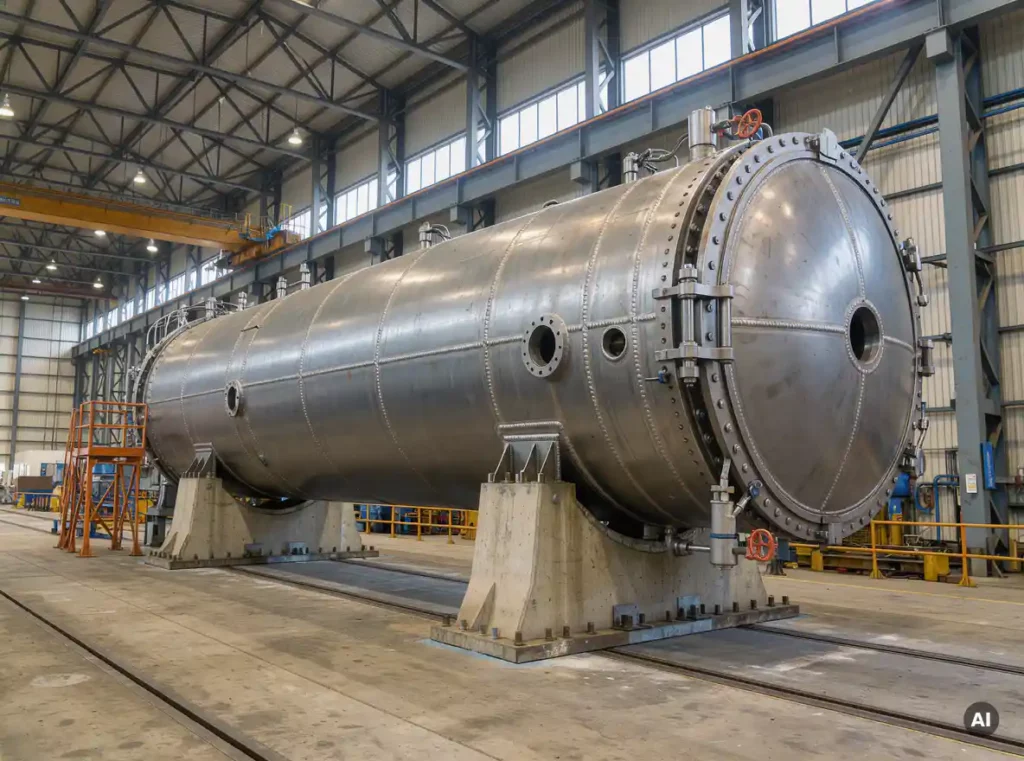
The filled weight of a mining autoclave directly sets the size, number and strength of its supports. Because the hydrotest load case, with the vessel completely flooded, is usually the heaviest the structure will ever carry, saddles, anchor bolts and foundations are sized for that condition rather than for normal operation. Thick walls, internal linings and slurry loads all add to it.
For a pressure leach or pressure oxidation autoclave that can reach several hundred tons, even small errors in assumed weight or load path can cause alignment problems and local stress. The sections below explain how filled weight is built up, which load cases matter and what buyers should specify.
What makes up an autoclave’s filled weight?
An autoclave’s filled weight is the sum of its empty fabricated weight, internals, insulation and attachments, plus the weight of the fluid that fills it. In a hydrotest this fluid is water at full volume. In operation it is a slurry at a defined fill level and density.
Each element matters for support design. The empty weight is dominated by the thick shell and heads, and for a clad autoclave it includes both the carbon steel base and the corrosion resistant lining. Compartment walls, agitators, nozzles, manways and brick or membrane linings add further load. Many autoclaves for nickel, cobalt and gold processing fall in the range of roughly 500 to 1,000 tons as built, so the contents come on top of an already very heavy structure.
The main contributors to filled weight include:
- Shell, heads and nozzles in carbon steel or other base material
- Clad layer or lining in titanium or another corrosion resistant material
- Internal compartments, baffles, agitator shafts and drive components
- Insulation, platforms, piping and other attachments
- Test water during hydrotest, or process slurry during operation
Water has a density of about 1,000 kg per cubic metre, while process slurry is often denser. The gap between these two cases can change the governing load, so both should be calculated rather than assumed.
Which load cases govern autoclave support design?
The governing load cases are normally the hydrotest condition, the normal operating condition and the empty condition during transport and erection. Hydrotest often produces the highest vertical load, while operation adds thermal growth, nozzle loads and dynamic effects from agitation. The support design must satisfy all of them.
A typical set of cases is worth listing in order of how engineers usually review them:
- Erection and lifting: the empty vessel is lifted and set, and local loads at lifting lugs and saddle contact areas can govern.
- Hydrotest: the vessel is completely filled with water, usually the maximum vertical load on saddles and the foundation.
- Normal operation: the vessel carries slurry at operating level, plus pressure, temperature and agitator loads.
- Upset and occasional loads: wind, seismic activity and piping reactions are added according to the site conditions and applicable code.
Seismic loads deserve particular attention for heavy equipment, because inertial forces scale with mass. A vessel at the upper end of the weight range attracts proportionally larger horizontal forces, which feed directly into anchor bolt and foundation design.
How does filled weight change saddle design?
Greater filled weight demands wider saddles, thicker wear or reinforcement plates and more carefully controlled contact angles, because the load transfers to the shell through a limited contact area. Heavy horizontal autoclaves usually need more than two supports, plus provisions for thermal expansion, to keep shell stresses within code limits.
Several design aspects change as weight increases:
Local shell stress at the saddle
The saddle reaction creates high local stresses in the shell, particularly at the horn of the saddle. Analyses such as the Zick method, or more detailed finite element analysis for unusual geometries, check this region. For thick-walled and clad shells, the analysis should account for how the lining interacts with the base shell.
Support arrangement and thermal movement
An autoclave grows in length when heated, so one saddle is typically fixed and the others are free to slide. Sliding supports need low friction surfaces that stay reliable under very high vertical loads. The friction force at these supports becomes a real design input for the fixed saddle and the foundation, and it increases directly with filled weight.
With heavier vessels, designers also consider load sharing between saddles. If foundation settlement or fabrication tolerance leaves one saddle carrying more than its share, local stresses rise quickly.
What foundation requirements does a heavy autoclave need?
A heavy autoclave needs a foundation designed for the full filled weight, with enough bearing capacity, stiffness and anchor bolt resistance to limit settlement and resist horizontal forces. Foundations are usually reinforced concrete, sized from the hydrotest and seismic load cases, and checked against site specific soil conditions.
Key requirements include:
- Bearing capacity: the soil under each pier or raft must carry the maximum load without excessive settlement.
- Differential settlement limits: settlement that differs between saddles can induce stress in the shell, so limits should be agreed with the vessel designer.
- Anchor bolt design: bolts must resist overturning, sliding and friction forces from thermal movement.
- Grouting and levelling: base plates need full, uniform contact so the load spreads as the designer assumed.
The hydrotest water also deserves planning. Test water weight is applied temporarily, but it can be the peak foundation load, so the foundation must be ready and cured before the vessel is filled.
How can support problems affect autoclave alignment and integrity?
Support problems such as uneven settlement, undersized saddles or restricted thermal movement can misalign nozzles, overload welds and raise local stresses in the shell. In an autoclave this can damage the lining, disturb agitator alignment and shorten service life, so supports are treated as part of the equipment’s integrity rather than civil work alone.
Practical consequences can include:
- Misalignment of agitator shafts, seals and drive systems, leading to wear and leakage
- Stresses at nozzle and piping connections beyond allowable limits
- Fatigue at saddle welds from repeated thermal cycles if sliding supports seize
- Strain on clad or lined surfaces, where erosion and corrosion are already critical concerns
Dimensional accuracy during fabrication matters here too. A vessel that is straight, round and correctly dimensioned sits evenly on its saddles, while distortion from welding or heat treatment of heavy sections can undermine even a well designed support system.
What should buyers specify to get supports right?
Buyers should specify the process fill density and level, hydrotest conditions, site seismic and wind data, allowable foundation settlement and the preferred support arrangement. Clear loads and interfaces let the fabricator and foundation designer work from the same assumptions and avoid costly changes late in the project.
A useful specification package covers:
- Operating, design and test conditions, including slurry density and maximum fill level
- Site data such as soil bearing information, seismic zone and wind loads
- Nozzle loads and piping reactions from the connected plant
- Required design codes and any supplementary analyses, such as finite element or fatigue studies
- Transport route limits, lifting methods and erection sequence
- Interface definitions for saddles, base plates, anchor bolts and grouting
Agreeing these points early reduces risk, because a change in fill density or seismic criteria after design can ripple through shell thickness, saddle design and foundation size.
How Coek helps with autoclave support requirements
Coek designs and fabricates large industrial autoclaves, with references approaching 1,000 tons, and treats supports as part of the mechanical design from the start. Customer process requirements are translated into manufacturable equipment, with attention to weight, load paths and fabrication accuracy.
- In-house mechanical engineering, including support and saddle design checks against the governing load cases
- Supplementary analyses such as finite element, fatigue and thermal studies where the design calls for them
- Experience with thick-walled and clad construction in titanium and other demanding materials
- Manufacturing capacity for equipment up to 10 metres in diameter and about 1,000 tons
- Design to international codes including ASME, PED and AD Merkblätter
To learn more about our industrial autoclaves or to discuss the support requirements of your project with an engineer, please contact our team.
Frequently Asked Questions
How do I get started calculating the filled weight of an autoclave for support design?
Start with the fabricator’s certified empty weight, including shell, heads, nozzles, cladding or lining, internals and attachments. Then calculate the internal volume and multiply by 1,000 kg/m³ for the hydrotest case, and by the specified slurry density and maximum fill level for the operating case. Run both cases and design to the higher value, and ask the vessel designer to confirm the numbers against the final weight report before saddles and foundations are frozen.
What if the process slurry is denser than water, so that operation governs over hydrotest?
This can happen with high-solids slurries, especially if the vessel is only partially filled during test or the density is well above 1,000 kg/m³. In that case operating loads, combined with thermal growth, agitator loads and seismic forces, may govern the saddles and anchor bolts. Always compare the two cases explicitly, and tell the fabricator early about any future increase in slurry density or fill level so the supports have margin.
How many saddles does a very heavy horizontal autoclave need?
Autoclaves at the upper end of the weight range often need more than two saddles to keep shell stresses and individual foundation loads within limits. The right number depends on length, shell thickness, internal compartment layout and the load per support. The vessel designer should check this with Zick-type analysis or finite element analysis, and the arrangement should provide one fixed saddle with the others free to slide.
How can I prevent sliding saddles from seizing under heavy loads?
Specify low-friction sliding surfaces rated for the full vertical load, such as PTFE-based or stainless-on-stainless bearing plates, and keep them clean and protected from slurry, dust and corrosion during construction and operation. Include the friction force in the design of the fixed saddle, anchor bolts and foundation. Inspect sliding supports during shutdowns, since seized supports restrict thermal growth and can cause fatigue at saddle welds.
How much differential settlement is acceptable between saddle foundations?
There is no universal figure, because the allowable value depends on shell stiffness, saddle spacing and nozzle and piping sensitivity. The limit should be agreed between the vessel designer and the foundation engineer, based on a stress check of the shell under a settled saddle condition. Monitor settlement during hydrotest, when the load is typically at its peak, so any problems appear before commissioning.
What are common mistakes in the support and foundation interface for autoclaves?
Frequent mistakes include designing foundations before the final weight is known, forgetting that the foundation must be fully cured before hydrotest filling, and leaving voids in the grout under base plates so that load is not spread as assumed. Other issues are ignoring friction forces from thermal movement and using seismic data that differs from the vessel design basis. A joint review of the interface drawings between the fabricator, civil engineer and owner helps avoid these problems.
Do supports need to be rechecked if the process conditions change after the design is complete?
Yes. A change in slurry density, fill level, operating temperature, seismic criteria or nozzle loads can affect saddle stresses, anchor bolt sizing and foundation design. Even a modest change can ripple through shell thickness and support design, so notify the fabricator as soon as it is known. Making the change during the engineering phase costs far less than modifying supports or foundations after fabrication or construction.