
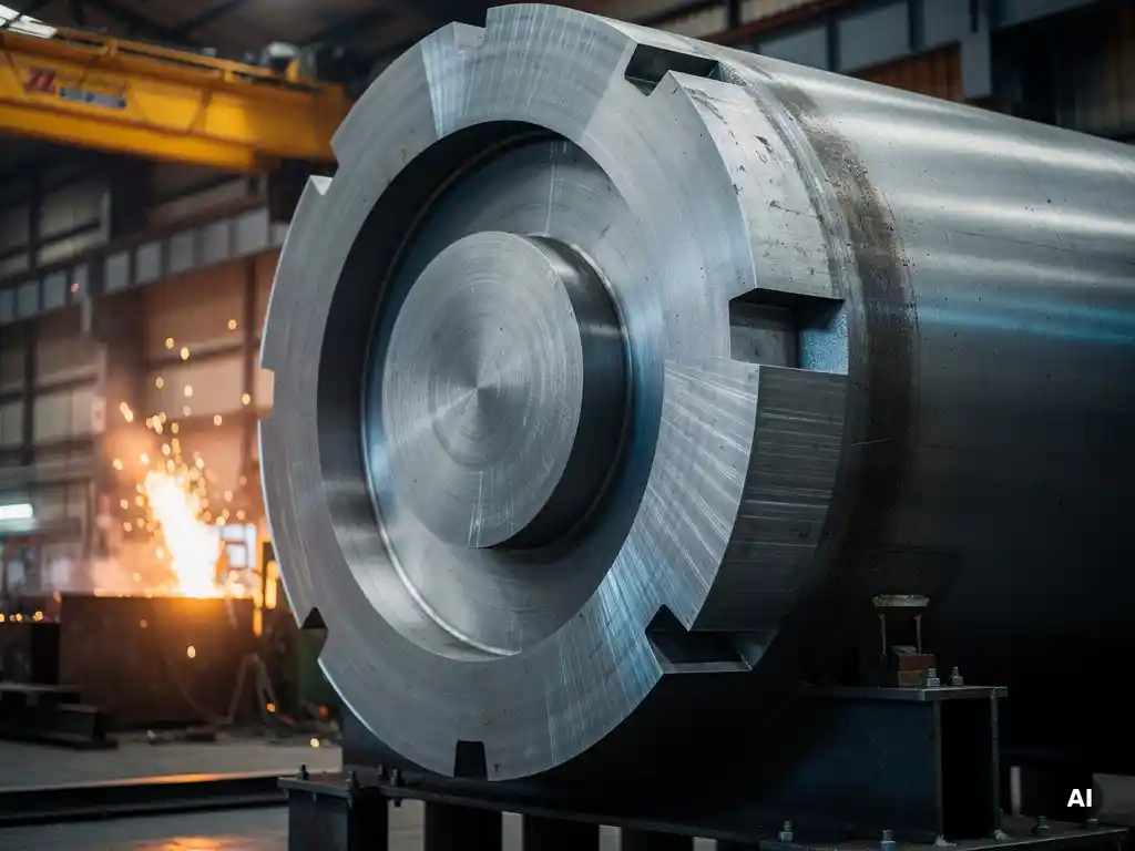
Wall thickness is one of the most critical factors in pressure vessel structural integrity. When wall thickness is insufficient, a vessel cannot safely contain its operating pressure, which can lead to plastic deformation, leakage, or catastrophic failure. The required thickness depends on operating pressure, vessel diameter, material strength, temperature, and corrosion conditions. The sections below unpack each of these variables in detail.
What happens to a pressure vessel when wall thickness is insufficient?
When wall thickness is insufficient, the vessel wall cannot resist the hoop stress generated by internal pressure. The shell begins to deform plastically, welds may crack, and in extreme cases the vessel ruptures. Even before visible failure, under-thickness can cause fatigue cracking over time, particularly at nozzles, welds, and geometric discontinuities.
The consequences are not always sudden. A vessel operating slightly below the required minimum wall thickness may perform acceptably for a period, but repeated pressure cycles accelerate fatigue damage. Elevated temperatures reduce material yield strength further, narrowing the safety margin even more. In corrosive environments, under-thickness combined with material loss from corrosion can bring a vessel to its structural limit well before its intended design life.
This is why pressure vessel design codes define minimum wall thickness as a hard lower boundary, not a guideline. Operating a vessel below that boundary is not a calculated risk, it is a structural liability.
How is minimum wall thickness calculated for a pressure vessel?
Minimum wall thickness for a pressure vessel is calculated using the design pressure, the vessel’s inner radius, the allowable stress of the chosen material, and a joint efficiency factor. The governing formula in most codes relates these variables so that the wall thickness is just sufficient to keep circumferential stress within the material’s safe working limit.
Under ASME Section VIII Division 1, the standard formula for cylindrical shells under internal pressure is:
t = (P × R) / (S × E – 0.6 × P)
Where t is the required minimum thickness, P is the design pressure, R is the inner radius, S is the maximum allowable stress for the material at design temperature, and E is the joint efficiency. The European PED framework follows EN 13445, which applies comparable logic with its own material and safety factor definitions.
The calculated minimum is a theoretical floor. In practice, engineers add a corrosion allowance, a mill undertolerance allowance, and sometimes a forming allowance on top of the calculated value before specifying the nominal wall thickness for fabrication.
Which factors determine the required wall thickness of a pressure vessel?
The required wall thickness of a pressure vessel is determined by a combination of mechanical, material, and process-related factors. No single variable drives the result in isolation. The most important factors are:
- Design pressure: Higher operating pressure directly increases the stress in the vessel wall, requiring greater thickness to stay within allowable limits.
- Vessel diameter: For the same pressure, a larger diameter vessel requires proportionally thicker walls because the total force acting on the shell increases with diameter.
- Material allowable stress: Stronger materials allow thinner walls for the same pressure and diameter. Material strength is temperature-dependent and drops at elevated operating temperatures.
- Design temperature: Higher temperatures reduce allowable stress values, which means the required wall thickness increases even if pressure remains constant.
- Weld joint efficiency: Lower joint efficiency factors, applied when radiographic examination is partial or absent, require additional wall thickness to compensate.
- Corrosion allowance: Expected material loss over the vessel’s service life must be added on top of the structurally calculated minimum.
- External loads: Wind, seismic, nozzle loads, and the vessel’s own weight create bending stresses that may govern wall thickness in certain sections.
How does corrosion allowance affect pressure vessel wall thickness?
Corrosion allowance is an additional thickness added to the structurally required minimum to account for material loss during service life. It is not part of the structural calculation itself, but it is added to the result before the nominal wall thickness is specified. A vessel designed for a 20-year service life in a mildly corrosive environment might carry a corrosion allowance of 1 to 3 mm, while aggressive chemical service can require significantly more.
The corrosion allowance is determined by the expected corrosion rate of the chosen material in the specific process environment, multiplied by the intended design life. This requires knowledge of the process fluid, its concentration, temperature, and flow conditions. When this data is uncertain, engineers apply conservative estimates to avoid premature retirement of the vessel.
In highly corrosive applications, an alternative to a large corrosion allowance is clad construction, where a carbon steel shell provides structural strength and a thin corrosion-resistant inner layer, such as titanium, zirconium, or a nickel alloy, handles the chemical environment. This approach can be more economical than specifying a fully solid corrosion-resistant wall at the required structural thickness. For more on custom pressure vessels design strategies, including clad construction, the product section covers these options in detail.
What is the difference between thick-walled and thin-walled pressure vessels?
The distinction between thick-walled and thin-walled pressure vessels is based on the ratio of wall thickness to vessel radius. A vessel is generally classified as thin-walled when the wall thickness is less than roughly one-tenth of the inner radius. When the ratio exceeds this threshold, the vessel is considered thick-walled and requires a different set of stress equations.
In thin-walled vessels, stress is assumed to be uniform across the wall thickness, and the simplified hoop stress formula applies with acceptable accuracy. In thick-walled vessels, stress varies significantly from the inner surface to the outer surface, with the highest stress concentration at the inner wall. This stress gradient must be accounted for using Lamé’s equations or equivalent formulations in the applicable design code.
Thick-walled construction is common in high-pressure reactors, autoclaves, and vessels operating at extreme pressures. These vessels demand more precise engineering, tighter fabrication tolerances, and more thorough inspection, because errors in wall thickness or weld quality have a greater impact on structural performance than in standard thin-walled equipment.
How does material choice influence required wall thickness?
Material choice directly influences required wall thickness because allowable stress, which is derived from material yield strength and tensile strength, is the denominator in the wall thickness calculation. A material with a higher allowable stress at operating temperature produces a lower required thickness for the same pressure and diameter.
For example, a high-strength low-alloy steel will allow a thinner wall than a standard carbon steel under identical design conditions. Conversely, corrosion-resistant alloys such as titanium or zirconium, while offering exceptional chemical resistance, may have lower allowable stress values than high-strength steels, which can increase the required wall thickness when used as solid construction.
This trade-off is one reason why clad construction is technically attractive in corrosive service. The structural calculation is based on the carbon steel backing material, which typically has favourable strength properties, while the thin corrosion-resistant layer contributes to chemical protection without needing to carry the full mechanical load. Material selection is therefore not only a corrosion decision but a structural and economic one as well.
When does wall thickness need to be verified beyond standard code calculations?
Standard code calculations cover the primary design case: internal pressure on a cylindrical or spherical shell under steady operating conditions. Wall thickness must be verified beyond these calculations when the vessel is subject to conditions that standard formulas do not fully address.
Situations that require additional analysis include:
- External pressure or vacuum service: Thin-walled vessels under external pressure are susceptible to buckling, which is governed by different mechanics than internal pressure failure and requires separate stability calculations.
- Cyclic loading: Vessels that experience repeated pressure cycles, thermal transients, or fluctuating mechanical loads require fatigue analysis to verify that the wall thickness and geometry are adequate over the intended number of cycles.
- Geometric discontinuities: Nozzle connections, head-to-shell junctions, and support attachments create local stress concentrations that may require finite element analysis to assess accurately.
- Elevated temperature creep: At very high operating temperatures, materials deform slowly under sustained stress. Standard allowable stress values may not capture this behavior, requiring time-dependent analysis.
- First-of-a-kind or unusually proportioned equipment: Vessels that fall outside the geometric scope of standard code formulas, or that combine multiple loading types simultaneously, benefit from detailed engineering analysis beyond the code minimum.
In all these situations, the governing failure mode may not be the one the standard formula was designed to prevent. Thorough engineering review ensures that the specified wall thickness addresses every relevant structural risk, not just the primary pressure case.
How Coek Engineering approaches pressure vessel wall thickness
At Coek Engineering, pressure vessel wall thickness is treated as an engineering outcome, not a default parameter. For every custom vessel, the required thickness is derived from the full set of design conditions, including pressure, temperature, material properties, corrosion environment, and any additional mechanical loads.
Coek’s approach to wall thickness and structural integrity includes:
- Translating customer process requirements into mechanically sound thickness specifications, including corrosion allowance and material selection
- Expertise in thick-walled construction for high-pressure vessels, reactors, and large-scale autoclaves
- Clad construction as an alternative to heavy solid-wall corrosion-resistant alloys, combining structural efficiency with chemical resistance
- Fabrication of vessels up to approximately 10 metres in diameter, where wall thickness, weight, and dimensional control present significant manufacturing challenges
- Compliance with ASME, PED, and other applicable international standards
If your project involves demanding pressure, temperature, or corrosion conditions where wall thickness decisions carry real consequences, contact Coek Engineering to discuss your specifications with our engineering team.
Frequently Asked Questions
How do I know if my existing pressure vessel still meets minimum wall thickness requirements?
The most reliable method is ultrasonic thickness (UT) testing, which measures remaining wall thickness at multiple points across the shell, heads, and nozzles without requiring the vessel to be taken out of service permanently. The measured values should be compared against the original minimum required thickness plus any remaining corrosion allowance defined in the design documentation. If measured thickness has dropped below the calculated structural minimum, the vessel must be re-rated to a lower operating pressure, repaired, or retired — continuing to operate it as-is is not a compliant option under ASME or PED frameworks.
What is the difference between nominal wall thickness and minimum required wall thickness?
Minimum required wall thickness is the theoretical floor produced by the design code formula — the absolute least amount of material needed to safely contain the design pressure at operating temperature. Nominal wall thickness is the value actually specified for fabrication, and it is always higher than the minimum required value because it incorporates additional allowances such as corrosion allowance, mill undertolerance (typically 12.5% for standard plate), and any forming thinning that occurs during head forming or rolling. Confusing the two is a common mistake: the nominal thickness stamped on a vessel datasheet does not represent the structural minimum — it represents the starting point before service life consumption begins.
Can I increase the operating pressure of an existing vessel by verifying that the actual wall thickness exceeds the original design minimum?
In principle, yes — this process is called re-rating, and it is permitted under ASME Section VIII and equivalent standards provided a formal engineering review is completed. The review must confirm that the measured wall thickness, adjusted for any corrosion already consumed, satisfies the code formula at the new, higher design pressure, and that all other components — nozzles, flanges, welds, and supports — are also adequate for the increased load. Re-rating must be documented, stamped, and in many jurisdictions approved by an authorized inspection agency; it cannot be done informally based on a thickness measurement alone.
What common mistakes do engineers make when specifying pressure vessel wall thickness?
One of the most frequent errors is applying the correct formula but using an allowable stress value at ambient temperature when the vessel will actually operate at elevated temperature, where allowable stress is significantly lower — this produces an unconservative and potentially unsafe result. Another common mistake is omitting or underestimating the corrosion allowance, particularly when process fluid data is incomplete or optimistic. Engineers also sometimes overlook mill undertolerance, specifying a nominal thickness equal to the calculated minimum without accounting for the fact that delivered plate can legally be thinner than the ordered size by up to 12.5%.
At what point should finite element analysis (FEA) be used instead of standard code formulas for wall thickness verification?
FEA becomes necessary when the geometry or loading conditions fall outside the assumptions that standard code formulas are built on — primarily uniform pressure on simple cylindrical or spherical shells. Practical triggers include complex nozzle configurations with high external loads, vessels with large diameter-to-thickness ratios under external pressure where buckling governs, head-to-shell junctions with unusual proportions, and any situation where stress concentrations at discontinuities need to be quantified rather than estimated with stress intensification factors. FEA is also the standard tool for fatigue life assessment when a vessel is subject to a defined number of pressure or thermal cycles over its design life.
How does joint efficiency affect wall thickness, and what inspection level is needed to achieve full joint efficiency?
Joint efficiency (E) appears in the denominator of the ASME wall thickness formula, so a lower value directly increases the required wall thickness to compensate for the assumed reduction in weld quality. Under ASME Section VIII Division 1, a joint efficiency of 1.0 — the highest value — requires full radiographic examination (RT) of all longitudinal and circumferential welds. Spot radiography yields an efficiency of 0.85, and no radiography drops it to 0.70. Choosing full radiography therefore allows a thinner specified wall and often reduces material costs enough to offset the additional inspection expense, particularly on larger or higher-pressure vessels.
Is there a minimum wall thickness for pressure vessels regardless of what the design formula produces?
Yes. Most design codes impose absolute minimum wall thickness values that apply even when the pressure formula calculates a lower result. Under ASME Section VIII Division 1, the minimum shell thickness after forming is generally 1/16 inch (approximately 1.6 mm) exclusive of corrosion allowance, though in practice fabrication and handling requirements push real-world minimums considerably higher. These code minimums exist because extremely thin shells are vulnerable to handling damage, weld distortion, and local buckling during fabrication and installation, regardless of what the pressure calculation alone would suggest.