
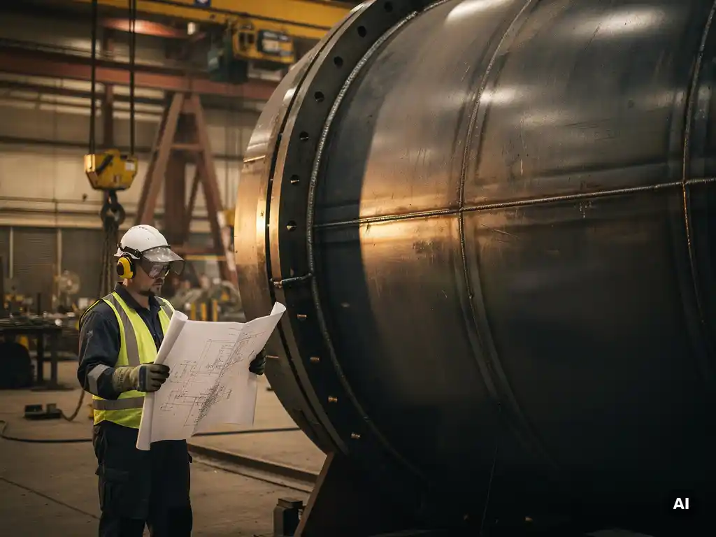
Sizing a pressure vessel for a high-pressure application requires calculating the minimum required wall thickness based on design pressure, vessel geometry, and the allowable stress of the chosen material, then verifying that the result complies with the applicable design code. The higher the operating pressure and the larger the vessel diameter, the greater the wall thickness demand, and beyond a certain threshold, design choices that are straightforward at moderate pressures become genuinely complex engineering decisions. The sections below address the most important questions engineers and procurement teams face when specifying high-pressure vessels.
What factors determine the wall thickness of a pressure vessel?
Wall thickness in a pressure vessel is primarily determined by four variables: the design pressure, the internal diameter, the allowable stress of the material at operating temperature, and a weld joint efficiency factor. The governing formula for cylindrical shells under internal pressure is well established in codes such as ASME VIII, and it shows that thickness increases proportionally with both pressure and diameter while decreasing as allowable stress rises.
In practice, several additional factors push the required thickness beyond the code minimum:
- Corrosion allowance: A dedicated material layer is added to compensate for anticipated metal loss over the vessel’s service life.
- Wind and seismic loads: Tall vertical vessels must account for external mechanical loads that add bending stress to the shell.
- Nozzle reinforcement: Openings in the shell interrupt the load path and require local reinforcement, which can influence the overall shell thickness.
- Fatigue and cyclic loading: Applications with frequent pressure or temperature cycles require additional thickness or design margin to prevent fatigue cracking.
- Cladding or lining requirements: When a corrosion-resistant inner layer is specified, the base material carries the structural load and must be sized accordingly.
At high pressures, even small increases in design pressure translate into significant additional wall thickness, which in turn affects weld procedures, heat treatment requirements, and the overall fabrication complexity of the vessel.
Which design codes apply to high-pressure vessel sizing?
The two most widely applied design codes for pressure vessel sizing internationally are the ASME Boiler and Pressure Vessel Code Section VIII (Divisions 1, 2, and 3) and the European Pressure Equipment Directive (PED) implemented through harmonised standards such as EN 13445. The applicable code depends on the country of installation, the client’s contractual requirements, and the pressure and temperature envelope of the application.
For high-pressure applications specifically, ASME VIII Division 2 and Division 3 are increasingly relevant. Division 2 applies a more rigorous analytical approach and allows higher allowable stresses than Division 1, making it the preferred choice for heavy-wall vessels where material efficiency matters. Division 3 applies to vessels operating above 690 bar (10,000 psi) and imposes additional requirements on fracture mechanics and fatigue analysis.
In European projects, EN 13445 provides equivalent analytical routes for high-pressure design, and many projects require dual compliance or at minimum alignment between the two frameworks. Regardless of which code governs, the fabricator must hold the relevant certification, such as an ASME U-stamp or PED conformity, before manufacturing can begin.
How does material selection affect pressure vessel sizing?
Material selection directly affects the required wall thickness because the allowable stress, the maximum stress the material is permitted to carry under design conditions, varies significantly between alloys. A material with a higher allowable stress at the operating temperature allows a thinner wall for the same pressure and diameter, reducing weight and fabrication cost. Conversely, a material with lower strength or reduced high-temperature performance requires a thicker shell.
Beyond mechanical strength, material selection for high-pressure vessels is driven by several other considerations:
Corrosion resistance is often the primary driver in process applications. Where the process fluid is aggressive, the engineer must either select a solid corrosion-resistant alloy or specify a clad construction, a carbon steel or low-alloy steel shell with a metallurgically bonded or weld-overlaid inner layer of a resistant material such as stainless steel, titanium, or a nickel alloy. Clad construction is frequently the most cost-effective route for large, thick-walled vessels, because it avoids using expensive alloys for the structural portion of the wall.
Weldability also matters. High-strength low-alloy steels and exotic alloys such as Hastelloy, Inconel, or zirconium require specific welding procedures, qualified welders, and often post-weld heat treatment. These requirements are built into the sizing and specification process, not added as an afterthought.
Temperature performance is critical in high-pressure applications that also involve elevated temperatures, because allowable stress values decrease as temperature rises. The designer must confirm that the selected material retains sufficient strength at the maximum design temperature, not only at ambient conditions.
What is the difference between design pressure and operating pressure in vessel sizing?
Operating pressure is the actual pressure at which the vessel runs during normal process conditions. Design pressure is a higher value used as the basis for all structural calculations, it incorporates a margin above the operating pressure to account for process upsets, pressure surges, instrument tolerances, and safety relief valve set points. In most codes, the design pressure is set at least 10% above the maximum allowable operating pressure, though the exact margin depends on the application.
This distinction matters because the vessel is physically sized to the design pressure, not the operating pressure. A vessel that operates at 100 bar may be designed for 115 bar or more, and its wall thickness, flange ratings, and relief valve sizing all reflect that higher value.
The maximum allowable working pressure (MAWP) is a related but distinct concept. The MAWP is the maximum pressure the completed vessel is permitted to sustain at its design temperature, calculated after fabrication based on actual dimensions and material properties. It must equal or exceed the design pressure. In practice, the MAWP often comes out slightly higher than the design pressure due to rounding and standard plate thicknesses selected during fabrication.
When should a pressure vessel be designed to ASME Division 2 instead of Division 1?
ASME VIII Division 2 should be considered when the vessel wall thickness required under Division 1 becomes impractical, when the project economics justify a more rigorous analysis in exchange for a thinner, lighter shell, or when the application involves fatigue, complex geometry, or detailed stress analysis that Division 1’s simplified rules cannot adequately address. Division 2 uses higher allowable stresses and requires more detailed engineering, including a formal design specification and a more thorough quality program.
The practical trigger for choosing Division 2 is often wall thickness. Division 1 uses conservative design rules that can result in walls that are difficult to weld, heat-treat, and inspect, particularly for large-diameter vessels at elevated pressures. Division 2’s analytical approach can reduce required thickness meaningfully, which simplifies fabrication and reduces material cost on heavy vessels.
Division 2 also becomes the appropriate choice when the design involves:
- Cyclic or fatigue-governed loading that requires a formal fatigue analysis
- Complex nozzle or head geometries that fall outside Division 1’s prescriptive rules
- High-temperature service where creep and time-dependent material behaviour must be assessed analytically
- Client or regulatory requirements that mandate a higher level of engineering documentation and traceability
Division 3 applies above 690 bar and introduces fracture mechanics requirements that go well beyond Division 2. It is reserved for genuinely extreme pressure applications and involves a substantially different engineering and fabrication approach.
How does vessel geometry influence sizing for high-pressure service?
Vessel geometry has a direct and significant effect on pressure vessel sizing. For a cylindrical shell under internal pressure, wall thickness is proportional to the inside radius, meaning that a larger-diameter vessel requires a thicker wall to contain the same pressure. This relationship means that high-pressure applications combined with large diameters produce the most demanding wall thickness requirements and the most complex fabrication challenges.
Head geometry is equally important. Hemispherical heads are the most efficient shape under pressure, requiring roughly half the wall thickness of a cylindrical shell for the same pressure. Ellipsoidal and torispherical heads are more common in practice because they are easier to fabricate, but they require greater thickness than hemispherical heads. At very high pressures, the choice of head geometry becomes a meaningful engineering and cost decision.
Vessel orientation also plays a role. Tall vertical vessels introduce additional stress from self-weight, wind, and seismic loads that must be combined with pressure loads in the structural analysis. Horizontal vessels on saddle supports experience local bending stresses at the support points that must be checked against allowable limits. These secondary loads do not change the fundamental pressure sizing, but they can require local reinforcement or increased shell thickness in specific zones.
What are the most common sizing mistakes in high-pressure vessel specifications?
The most common sizing mistakes in high-pressure vessel specifications fall into a consistent pattern: underspecifying the design margin, selecting materials based on cost alone, and treating the pressure vessel calculation as a standalone exercise rather than as part of an integrated design process. Each of these errors can result in a vessel that is technically non-compliant, difficult to fabricate, or inadequate for its service life.
Specific mistakes that appear repeatedly in practice include:
- Setting design pressure too close to operating pressure: Insufficient margin leaves no room for process upsets and can result in frequent relief valve actuation or vessel overpressure events.
- Omitting or underestimating corrosion allowance: A vessel sized for pressure alone, without adequate corrosion allowance, may reach its minimum allowable thickness well before the intended service life.
- Specifying materials without confirming weldability and fabrication feasibility: Some alloys that perform well in service are extremely difficult to weld at the thicknesses required for high-pressure applications.
- Ignoring nozzle loads in the shell sizing: External loads from connected piping can generate stresses at nozzle connections that exceed the local capacity of a shell sized for pressure alone.
- Applying Division 1 rules to applications that require Division 2 analysis: Using simplified rules for complex geometries or cyclic applications can result in non-conservative designs that fail to meet code intent.
- Failing to align the design code with the country of installation: A vessel certified under ASME but installed in a jurisdiction requiring PED compliance, or vice versa, can create significant regulatory and project delays.
The most effective way to avoid these errors is to involve an experienced mechanical engineer early in the specification process, before the design basis is fixed and before equipment enquiries go to market.
How Coek helps with high-pressure vessel sizing and design
Coek Engineering translates demanding process requirements into mechanically sound, manufacturable pressure equipment, including thick-walled, large-diameter and high-pressure vessels where standard fabrication approaches are insufficient. Working from customer or EPC-provided process specifications, Coek’s in-house engineering team addresses the full range of sizing and design considerations described above: wall thickness calculation, design code selection, material qualification, clad construction, and compliance with ASME and PED requirements.
Key capabilities relevant to high-pressure vessel projects include:
- In-house mechanical engineering to support design pressure, geometry, and material decisions
- Advanced materials expertise including solid and clad constructions with titanium, Hastelloy, Inconel, zirconium, and other demanding alloys
- Large-scale manufacturing for vessels up to 10 metres in diameter and approximately 1,000 tons
- Compliance with ASME (U-stamp) and PED certification requirements
- More than 30 years of experience with clad construction for corrosion-critical, high-pressure applications
If you are specifying a high-pressure vessel and want to discuss your technical requirements with an experienced fabrication partner, get in touch with Coek Engineering directly.
Frequently Asked Questions
How do I know if my application requires a formal fatigue analysis as part of the vessel sizing process?
A formal fatigue analysis is generally required when the vessel will experience significant pressure or temperature fluctuations over its service life — typically defined in ASME VIII Division 2 as more than 1,000 full pressure cycles, or fewer cycles at high stress amplitudes. If your process involves frequent startups and shutdowns, batch operations, or thermal cycling, you should flag this early in the design basis so the engineer can determine whether a fatigue assessment governs the design. Ignoring cyclic loading in the specification stage is one of the more consequential oversights in high-pressure vessel design, as it can require a complete redesign if identified late.
What is a realistic lead time for a high-pressure, thick-walled pressure vessel, and what drives the schedule?
Lead times for heavy-wall, high-pressure vessels typically range from 6 to 18 months depending on vessel size, material, design complexity, and fabricator workload. The longest schedule drivers are usually material procurement — particularly for thick clad plate or exotic alloys such as Hastelloy or titanium — and post-weld heat treatment, which can require extended furnace time for thick carbon or low-alloy steel shells. Engaging a fabricator early in the project, ideally at the design basis stage, allows material to be reserved and long-lead items to be identified before the engineering is complete.
Can a pressure vessel designed to ASME standards be used in a European country that requires PED compliance?
Not automatically. ASME certification (U-stamp) and PED conformity are separate regulatory frameworks, and a vessel manufactured to ASME standards must still demonstrate compliance with the Essential Safety Requirements of the PED before it can be placed into service in the European Economic Area. In practice, many fabricators with both ASME and PED certification can design and build to both frameworks simultaneously, but this must be agreed at the specification stage — not resolved after manufacturing is complete. Misalignment between the governing code and the country of installation is a common source of project delays.
What is clad construction, and when is it more cost-effective than using a solid corrosion-resistant alloy?
Clad construction combines a structural base material — typically carbon steel or low-alloy steel — with a thin metallurgically bonded or weld-overlaid inner layer of a corrosion-resistant alloy such as stainless steel, titanium, or a nickel alloy. The base material carries the full mechanical load, and the cladding provides the corrosion barrier, meaning expensive alloy is only used where it is functionally necessary. For large-diameter, thick-walled vessels, clad construction is almost always more cost-effective than solid alloy construction because the structural wall thickness required at high pressures would make a solid exotic-alloy vessel prohibitively expensive and extremely difficult to fabricate.
How should corrosion allowance be determined, and who is responsible for specifying it?
Corrosion allowance is the additional wall thickness added beyond the structural minimum to compensate for material loss over the vessel’s intended service life, and it is the process or corrosion engineer’s responsibility to specify it — not the vessel fabricator’s. It should be based on the corrosivity of the process fluid, the expected corrosion rate for the selected material in that environment, and the planned inspection interval and design life of the vessel. A common default of 3 mm is often applied without analysis, but in aggressive services this can be significantly insufficient; in services where the cladding provides full corrosion protection, a reduced or zero corrosion allowance on the base material may be appropriate.
At what point in a project should a pressure vessel fabricator be brought into the design process?
Ideally, a fabricator with in-house engineering capability should be consulted during the design basis or FEED (Front-End Engineering Design) phase, before wall thickness calculations are finalised and before equipment enquiries go to market. Early fabricator involvement allows manufacturing constraints — such as plate availability in specific thicknesses, rolling and forming limits for heavy plate, or weld procedure qualifications for exotic alloys — to be incorporated into the design rather than discovered as problems during procurement. For high-pressure vessels in particular, late-stage design changes driven by fabrication feasibility are costly and can affect project schedules significantly.
What inspections and testing are typically required for a high-pressure vessel before it is released for service?
High-pressure vessels are subject to a defined inspection and testing program that is specified by the applicable design code and agreed in the quality plan before fabrication begins. This typically includes non-destructive examination (NDE) of welds — radiographic testing (RT) or ultrasonic testing (UT) depending on the joint category and code division — hardness testing after post-weld heat treatment, hydrostatic pressure testing at 1.3 to 1.5 times the design pressure, and dimensional and material certification checks. For clad vessels, bond integrity testing of the cladding is also required. Division 2 and Division 3 vessels carry more stringent NDE and documentation requirements than Division 1, reflecting the higher allowable stresses and more demanding service conditions they are designed to handle.