
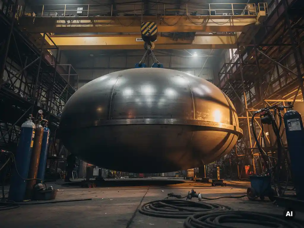
Operating pressure is one of the most decisive factors in pressure vessel head geometry selection. Hemispherical heads handle the highest operating pressures most efficiently, while ellipsoidal, torispherical, and flat heads suit progressively lower pressure ranges. The sections below unpack each aspect of this relationship, from wall thickness implications to the role of design codes and material properties.
Which head geometry handles the highest operating pressures?
Hemispherical heads handle the highest operating pressures of any standard pressure vessel head geometry. Because a hemisphere distributes stress uniformly across its curved surface, it requires the least wall thickness for a given pressure and diameter. This makes it the most structurally efficient choice when operating pressures are severe or when weight and material savings at high pressure are a priority.
Ellipsoidal heads come second in pressure-handling capability. Their semi-elliptical profile provides good stress distribution and suits a wide range of medium-to-high-pressure applications without the fabrication complexity of a full hemisphere. Torispherical heads, which combine a spherical crown with a knuckle radius, are suitable for moderate pressures. Flat heads, by contrast, are inherently the weakest geometry under internal pressure and are only practical at low pressures or small diameters.
How does operating pressure change the required wall thickness of a head?
As operating pressure increases, the required wall thickness of a pressure vessel head increases proportionally. The relationship is governed by the design pressure, the allowable stress of the chosen material, and a geometry-dependent stress factor. Flatter geometries require disproportionately more material to resist the same pressure compared to curved geometries.
For hemispherical heads, the required thickness is roughly half that of a cylindrical shell at the same pressure and diameter, because the stress is shared equally in two directions. Ellipsoidal heads approach this efficiency depending on their aspect ratio. Torispherical heads introduce localized bending stresses at the knuckle, which can drive thickness requirements up under higher pressures. Flat heads develop bending stresses across their entire face, making thickness grow rapidly as pressure or diameter increases.
What is the difference between ellipsoidal and torispherical heads?
An ellipsoidal head has a profile that follows a semi-ellipse, typically with a 2:1 ratio between the major and minor axes, giving it a smooth, continuously curved surface. A torispherical head is formed from two distinct radii: a large spherical crown radius and a smaller knuckle radius at the transition to the shell. The key difference is geometry, and that geometry directly affects stress distribution, fabrication cost, and pressure rating.
- Ellipsoidal heads offer better stress distribution, handle higher pressures more efficiently, and are the standard choice for medium-to-high-pressure vessels.
- Torispherical heads are less expensive to form and suit lower-to-moderate-pressure applications where the localized stresses at the knuckle remain within acceptable limits.
- Fabrication: Torispherical heads are generally easier and cheaper to press, making them common in cost-sensitive or lower-pressure designs.
- Stress concentration: The knuckle region of a torispherical head concentrates stress, which must be carefully evaluated under pressure cycling or elevated temperatures.
In practice, ellipsoidal heads are preferred when pressure is the dominant design driver, while torispherical heads are chosen when pressure is moderate and fabrication economy matters.
At what pressure does a flat head become impractical?
Flat heads become impractical at relatively modest pressures, particularly as vessel diameter increases. Because a flat head resists internal pressure through bending rather than membrane action, the required thickness rises sharply with both pressure and diameter. For large-diameter vessels, a flat head can become so thick that it is heavier and more expensive than a curved alternative, often making it structurally and economically unjustifiable.
Flat heads are typically used in small-diameter, low-pressure applications, or in specific configurations such as heat exchanger channel covers where access requirements justify the geometry. As a general principle, once the combination of pressure and diameter demands a flat head thickness that approaches or exceeds the shell wall thickness significantly, a curved geometry almost always becomes the more rational choice from both an engineering and a cost perspective.
How does vessel diameter interact with pressure in head selection?
Vessel diameter amplifies the effect of operating pressure on head geometry selection. For a given pressure, a larger diameter produces higher total force on the head, which drives up the required wall thickness regardless of geometry. This interaction means that a head geometry that is practical at small diameters can become structurally problematic or prohibitively heavy at large diameters under the same pressure.
For large-diameter, high-pressure vessels, the hemispherical or ellipsoidal head is almost always the engineering choice because their curved geometry converts pressure loads into membrane tension rather than bending. Flat heads scale particularly poorly with diameter: doubling the diameter at constant pressure can require a disproportionate increase in head thickness. This is why custom pressure vessels at large scale are almost never designed with flat heads unless there is a specific functional reason.
What role do material properties play in head geometry decisions?
Material properties directly influence which head geometry is structurally sufficient and practically manufacturable. The allowable stress of a material at operating temperature sets the baseline for how much wall thickness is needed for any given geometry. Higher-strength materials reduce required thickness, while materials with lower allowable stress or elevated-temperature derating require more.
Beyond strength, two material properties are particularly relevant to head geometry decisions:
- Formability: Hemispherical and ellipsoidal heads require more severe forming operations than torispherical heads. Materials such as titanium, zirconium, or thick-walled clad plate impose significant constraints on forming radius and process, which can influence whether a particular curved geometry is manufacturable within acceptable quality limits.
- Corrosion resistance: In corrosive environments, the inner surface geometry affects how protective linings or clad layers are applied and welded. Complex curvatures require careful fabrication planning to maintain the integrity of corrosion-resistant layers through the forming and welding process.
For equipment operating with advanced or exotic materials, geometry selection and material selection must be developed in parallel rather than sequentially.
Which design codes govern pressure vessel head geometry requirements?
Pressure vessel head geometry requirements are governed by internationally recognized design codes that specify calculation methods, allowable stresses, geometry constraints, and fabrication standards. The most widely applied codes are ASME Section VIII (used in the United States and many international projects), the European Pressure Equipment Directive (PED) implemented through EN 13445, and various national standards depending on the installation country.
These codes define the acceptable geometries, the stress formulas applicable to each head type, minimum thickness requirements, and the conditions under which geometry-specific stress concentration factors must be applied. For hemispherical, ellipsoidal, and torispherical heads, the codes provide explicit calculation routes. Flat heads require separate bending-based calculations that reflect their fundamentally different load-carrying mechanism. Compliance with the applicable code is not optional: it is a contractual and legal requirement for pressure equipment placed into service, and the choice of head geometry must be documented and verified within the code framework.
How Coek supports pressure vessel head geometry selection
Selecting the right head geometry requires more than applying a formula. It demands a clear understanding of operating pressure, diameter, material behavior, fabrication constraints, and applicable design codes, all evaluated together before a design is fixed.
Coek Engineering supports technically demanding pressure vessel projects by combining in-house mechanical engineering with specialized fabrication capabilities. For projects where head geometry selection is non-trivial, Coek’s approach includes:
- Translating customer process requirements into mechanically compliant and manufacturable head designs
- Engineering for advanced and demanding materials, including clad constructions and exotic alloys
- Large-scale fabrication capability for vessels where diameter and pressure interact to create significant design challenges
- Compliance with ASME, PED, and other applicable international standards
If your project involves pressure vessels where operating conditions, dimensions, or materials place conventional solutions under pressure, contact Coek Engineering to discuss your requirements.
Frequently Asked Questions
Can I switch head geometry on an existing pressure vessel during a retrofit or re-rating?
Switching head geometry on an existing vessel is technically possible but requires a full re-evaluation under the applicable design code, since the new geometry will have different thickness requirements, stress distributions, and weld joint configurations. The shell-to-head junction, nozzle placements, and support structures may all need to be reassessed or modified. In many cases, a geometry change during re-rating is only justified when the original head has reached the end of its service life or when a significant operating pressure increase makes the original geometry structurally insufficient.
How does pressure cycling or fatigue affect the choice between torispherical and ellipsoidal heads?
Pressure cycling introduces fatigue loading, and the knuckle region of a torispherical head is a known stress concentration point that can initiate fatigue cracks under repeated pressurization and depressurization. Ellipsoidal heads, with their smoother stress distribution, are generally more fatigue-resistant and are the preferred choice when vessels are subject to frequent or severe pressure cycling. If a torispherical head must be used in a cyclic application, the knuckle geometry and thickness should be carefully evaluated against the fatigue curves provided in the applicable design code.
What is the most common mistake engineers make when selecting a head geometry early in a project?
The most common mistake is selecting head geometry based on pressure alone, without simultaneously considering vessel diameter, material formability, and fabrication constraints. A geometry that appears optimal on paper can become impractical or prohibitively expensive once the actual plate thickness, forming radius limitations, and available manufacturing equipment are factored in. Head geometry selection should always be treated as a multi-variable decision made in close coordination with the fabricator, not a purely analytical exercise performed in isolation.
Are there situations where a flat head is actually the better engineering choice over a curved head?
Yes — flat heads are the rational choice in specific functional configurations, regardless of their pressure inefficiency. Heat exchanger channel covers, manway closures, and equipment requiring frequent access or internal inspection often use flat heads because they can be bolted, removed, and reinstalled without compromising the vessel shell. In small-diameter, low-pressure applications, the fabrication simplicity and lower cost of a flat head can also outweigh the material savings offered by a curved geometry, making it the more practical and economical solution.
How do external pressure conditions, such as vacuum service, change head geometry selection compared to internal pressure?
Under external pressure or vacuum service, the failure mode shifts from tensile overstress to elastic buckling, which fundamentally changes how head geometry should be evaluated. Hemispherical heads remain efficient under external pressure, but torispherical and ellipsoidal heads become more susceptible to buckling in the knuckle and crown regions, and their required thickness under vacuum can be significantly greater than under equivalent internal pressure. Design codes such as ASME Section VIII Division 1 provide separate calculation procedures for external pressure, and geometry selection for vacuum service should always be verified against these buckling-specific rules rather than the internal pressure formulas.
How does the choice of head geometry affect welding and inspection requirements during fabrication?
Head geometry directly influences the complexity and accessibility of the shell-to-head weld, which is one of the most critical joints in a pressure vessel. Hemispherical heads, due to their depth, can make radiographic or ultrasonic inspection of the circumferential seam more challenging and may require specialized positioning during welding. Torispherical and ellipsoidal heads offer a more accessible weld zone but still require full compliance with the non-destructive examination requirements specified by the applicable code. The geometry also affects how internal weld surfaces are dressed or inspected for corrosion-resistant linings, particularly in clad or lined vessel constructions.
At what point in a project should head geometry be formally locked in, and who should be involved in that decision?
Head geometry should be formally locked in during the detailed engineering phase, after process conditions, operating pressure range, vessel diameter, material selection, and applicable design code have all been confirmed — but before detailed fabrication drawings are issued. The decision should involve the mechanical or vessel engineer, the fabricator, and, where applicable, the materials specialist, since formability constraints and shop capabilities can override what is theoretically optimal. Locking in geometry too early, before these inputs are stable, is a frequent source of costly design revisions later in the project.
Related Articles
- How does pressure cycling affect the design life of industrial pressure vessels?
- How do you size a pressure vessel for a high-pressure application?
- How do you control dimensional accuracy in large pressure vessel fabrication?
- What is a high pressure autoclave used for in chemical processing?
- How do you verify the integrity of a clad layer in a pressure vessel after fabrication?