
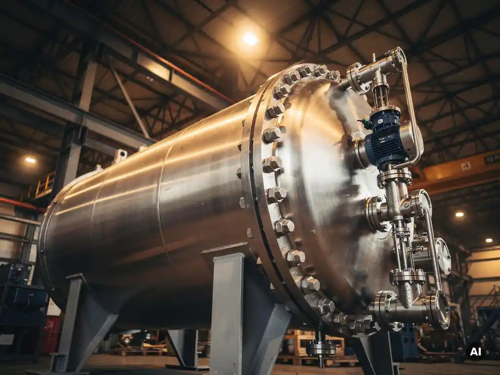
High-pressure industrial autoclaves require a layered set of safety systems, including pressure relief devices, rupture discs, safety interlocks, emergency shutdown logic, and pressure monitoring instrumentation. These systems work together to prevent overpressure, uncontrolled reactions, and structural failure. The specific combination depends on operating pressure, temperature, process chemistry, and the applicable regulatory framework.
Because autoclaves operate at the intersection of high pressure, elevated temperature, and often corrosive or reactive media, the consequences of a safety system failure are severe. Every large autoclave project therefore demands that safety systems be specified, engineered, and validated with the same rigour as the pressure-containing structure itself. The sections below address the most common questions that engineers and procurement teams ask when specifying autoclave safety requirements.
What types of safety devices are installed on high-pressure autoclaves?
High-pressure autoclaves are equipped with several categories of protective devices. The primary overpressure protection devices are safety relief valves and rupture discs. These are supported by pressure transmitters, temperature sensors, level indicators, and flow monitoring instruments that feed into the control and shutdown logic of the system.
A typical safety device package for a large industrial autoclave includes:
- Safety relief valves (SRVs): Spring-loaded or pilot-operated valves that open automatically when pressure exceeds the set point and reclose once pressure returns to an acceptable level.
- Rupture discs: Non-reclosing pressure relief devices installed upstream of or in combination with SRVs, providing a fast-acting, leak-free barrier under normal operating conditions.
- Pressure transmitters and gauges: Continuous monitoring of vessel pressure, feeding both the control system and independent safety logic.
- Temperature sensors: Thermocouples or resistance temperature detectors (RTDs) positioned at critical points inside and outside the vessel.
- Level and flow instruments: Monitoring of feed, product, and coolant streams to detect abnormal process conditions before they escalate.
- Emergency isolation valves: Remotely actuated valves that can isolate the autoclave from feed or discharge streams on demand or when automatically triggered.
The selection and sizing of each device depend on the specific hazard scenarios identified during the process hazard analysis (PHA) or HAZOP study conducted for the installation.
How does a pressure relief system on an industrial autoclave work?
A pressure relief system on an industrial autoclave works by providing a controlled, pre-determined path for process fluid or gas to escape when vessel pressure exceeds the maximum allowable working pressure (MAWP). The system activates automatically, without operator intervention, and is sized to handle the worst credible overpressure scenario.
In practice, the relief system is designed around a specific set of overpressure scenarios, which may include blocked outlet, external fire, runaway reaction, or utility failure. The relief valve or rupture disc is sized to vent sufficient mass flow to prevent the vessel pressure from rising above the design limit, even under the most demanding of those scenarios.
Rupture discs are often installed in series with safety relief valves on autoclaves handling corrosive media. The disc protects the valve seat from process chemistry during normal operation, ensuring the valve remains functional. When the disc bursts, the valve opens and controls the discharge rate. A pressure indicator between the disc and valve monitors for disc failure or leakage, which would otherwise go undetected.
The discharge from the relief system is typically routed to a closed collection system, a scrubber, or a flare, depending on the hazard classification of the process fluid. Open atmospheric venting is generally not acceptable for toxic, flammable, or corrosive autoclave media.
What are the regulatory standards that govern autoclave safety systems?
The regulatory standards that govern industrial autoclave safety systems depend on the geographic location of the installation and the classification of the equipment. In Europe, the Pressure Equipment Directive (PED 2014/68/EU) is the primary framework. In North America, ASME Section VIII governs pressure vessel design and is complemented by ASME Section I for fired equipment and relevant OSHA process safety management regulations.
Beyond the pressure equipment standards themselves, autoclaves installed in hazardous process environments are subject to additional layers of regulation. In Europe, the ATEX directive applies where explosive atmospheres may be present. Process safety management frameworks such as OSHA PSM (in the United States) or the Seveso III Directive (in Europe) impose requirements on hazard identification, relief system design, and management of change for high-hazard installations.
For industrial autoclaves used in mining applications such as high-pressure acid leaching (HPAL) or pressure oxidation (POX), national mining safety regulations also apply, and these vary significantly between jurisdictions. Projects in Australia, Canada, and various African countries each carry their own regulatory overlays on top of the base pressure equipment standard.
International standards from ISO and the relevant national bodies also address specific aspects of safety instrumented systems. IEC 61511 (Functional Safety for the Process Industry) defines how safety instrumented systems (SIS) must be designed, validated, and maintained to achieve a defined safety integrity level (SIL).
What interlocks and shutdown logic are required for high-pressure autoclaves?
High-pressure autoclaves require a set of process interlocks and an emergency shutdown (ESD) system that can bring the vessel to a safe state without operator action when abnormal conditions are detected. The specific interlocks depend on the process, but high pressure, high temperature, low coolant flow, and agitator failure are among the most commonly specified trip conditions.
Interlocks are typically implemented at two levels. The basic process control system (BPCS) handles normal regulatory control and raises alarms when process variables deviate from setpoints. The safety instrumented system (SIS) operates independently of the BPCS and executes the shutdown logic when a defined trip condition is confirmed. This separation is a fundamental requirement of IEC 61511 and ensures that a failure in the control system cannot simultaneously disable the protective system.
Common autoclave interlock triggers include:
- High-high pressure: Triggers ESD and isolates feed streams if vessel pressure exceeds the high-high setpoint, which is set below the relief valve opening pressure.
- High-high temperature: Activates emergency cooling or isolates heat input to prevent runaway conditions.
- Agitator failure: In autoclaves with internal agitation, loss of agitator function can cause localised hot spots or reaction accumulation, triggering a controlled shutdown.
- Low coolant flow: Detected by flow transmitters on cooling circuits, initiating shutdown if cooling capacity is lost.
- Rupture disc failure signal: Pressure detected between a rupture disc and safety valve triggers an alarm and may initiate shutdown to allow safe inspection.
The SIL rating required for each safety function is determined through a risk assessment, typically a layer of protection analysis (LOPA), conducted during the project’s process safety phase.
How does autoclave design affect the effectiveness of safety systems?
Autoclave design directly affects how well safety systems can perform their function. The nozzle layout, wall thickness, material selection, and internal geometry all influence where relief devices can be placed, how quickly pressure can be vented, and whether instrumentation can accurately sense the conditions it is meant to monitor.
Nozzle placement is a practical example. Relief valves and rupture discs must be positioned to sense the highest pressure point in the vessel and to vent vapour rather than liquid where possible. In large horizontal autoclaves, this means nozzle placement on the top of the vessel along its length must be considered carefully during the mechanical design phase, not added as an afterthought.
Material selection for the vessel also has safety implications. Autoclaves operating in corrosive environments, such as those used in HPAL or POX processes, are often constructed with titanium-clad or solid titanium internals. If the safety nozzles and their connections are not specified in compatible materials, corrosion can compromise the integrity of the relief device seat or the instrument connection over time, leading to unreliable performance precisely when it matters most.
Wall thickness and the resulting thermal mass of a large autoclave affect how quickly the vessel responds to emergency cooling. A vessel approaching 1,000 tons in weight, such as those Coek has fabricated for gold extraction applications, stores a significant amount of thermal energy. The ESD cooling strategy must account for this in both the design of the cooling system and the shutdown sequencing logic.
Dimensional precision in fabrication is also relevant. Flanged connections for safety-critical instruments and relief devices must meet tight tolerances to ensure reliable sealing under cyclic pressure and temperature loading. This is an area where fabrication quality directly supports safety system reliability.
Who is responsible for specifying safety systems on a custom autoclave project?
On a custom autoclave project, responsibility for specifying safety systems is shared across multiple disciplines and organisations. The technology owner or process licensor defines the process hazards and the required protective functions. The EPC contractor or engineering firm translates these into instrument and interlock specifications. The autoclave manufacturer is responsible for ensuring the vessel design accommodates those specifications without compromising structural integrity or fabrication quality.
In practice, the technology owner or the client’s process safety team leads the HAZOP and LOPA studies that identify the required safety functions and their SIL targets. The SIS engineering team then designs the instrumented protective layers. The mechanical equipment manufacturer, working from the process datasheet and the instrument nozzle schedule, must ensure that every safety-critical connection is correctly positioned, correctly rated, and fabricated in the appropriate material.
Misalignment between these groups is a common source of problems on complex autoclave projects. If the safety nozzle schedule is issued late, or if the process team changes a trip setpoint without informing the mechanical designer, the vessel may need modification after fabrication has begun. Early and structured coordination between the process, instrumentation, and mechanical engineering disciplines avoids these conflicts and ensures that the safety systems specified on paper can actually be installed and operated on the equipment as built.
For custom pressure equipment, the manufacturer’s in-house engineering capability plays a meaningful role in this coordination. A fabricator who understands both the mechanical design constraints and the safety system requirements can flag conflicts early and propose solutions that satisfy both the process safety intent and the fabrication requirements.
How Coek supports safety-critical autoclave projects
Coek Engineering manufactures large, custom industrial autoclaves for demanding high-pressure and high-temperature applications, including HPAL, POX, and other corrosive process environments. The in-house engineering team works directly from customer process requirements and instrument schedules, ensuring that safety-critical nozzles, relief device connections, and instrument points are correctly integrated into the mechanical design from the outset.
Key aspects of how Coek approaches safety-critical autoclave fabrication:
- Mechanical design aligned with customer-specified safety nozzle schedules and relief device requirements
- Advanced materials expertise, including titanium-clad and solid titanium construction, ensuring corrosion integrity at safety-critical connections
- Fabrication of autoclaves up to approximately 1,000 tons, with dimensional precision suited to demanding flange and instrument connections
- Compliance with PED, ASME, and other applicable international standards
- Experience coordinating with EPC contractors and technology owners on complex, multi-discipline projects
If you are specifying a large autoclave for a technically demanding process, contact Coek Engineering to discuss your mechanical and fabrication requirements.
Frequently Asked Questions
How do we determine the correct sizing for a safety relief valve on a high-pressure autoclave?
Relief valve sizing is driven by the worst-case credible overpressure scenario identified during your HAZOP or PHA study — common scenarios include blocked outlet, external fire, and runaway reaction. The required relieving capacity (in mass flow or volumetric flow) is calculated for each scenario, and the valve is sized to the largest demand case using the applicable standard, typically API 520/521 in North America or ISO 4126 in Europe. It is critical to account for the physical state of the relieving fluid (vapour, liquid, or two-phase) at relieving conditions, as this significantly affects the calculated orifice area. Engaging a process safety engineer with specific autoclave experience early in the design phase prevents undersizing errors that are costly to correct after fabrication.
What is the difference between a Safety Instrumented System (SIS) and a Basic Process Control System (BPCS), and why does it matter for autoclave safety?
The BPCS handles routine regulatory control — maintaining pressure, temperature, and flow at desired setpoints — while the SIS is an independent, dedicated layer that executes shutdown actions when the BPCS fails or process conditions exceed safe limits. IEC 61511 requires these two systems to be architecturally separate so that a single failure cannot simultaneously disable both control and protection. For a high-pressure autoclave, this means the trip sensors, logic solvers, and final elements (such as isolation valves) used in the SIS must not be shared with the BPCS, and the SIS must be periodically proof-tested to verify it will actually function when demanded.
What are the most common mistakes made when integrating safety systems into a custom autoclave design?
The most frequent mistake is treating safety system integration as a late-stage activity — issuing the instrument nozzle schedule after the vessel design is already advanced, which forces expensive modifications or compromises on nozzle placement. A related error is specifying safety nozzle materials that are incompatible with the process chemistry, particularly in corrosive environments like HPAL or POX, where a standard carbon steel flange on a titanium-clad vessel can become a corrosion failure point at a safety-critical connection. A third common issue is failing to align trip setpoints between the process safety team and the mechanical designer, resulting in high-high pressure settings that are too close to — or inadvertently above — the relief valve set pressure.
How often do safety devices on high-pressure autoclaves need to be tested and inspected?
Testing and inspection frequencies are governed by a combination of regulatory requirements, the SIL rating of each safety function, and the manufacturer’s recommendations. Safety relief valves are typically bench-tested and recertified on intervals ranging from one to five years depending on the process severity and jurisdictional requirements. SIS proof testing intervals are set during the SIL verification process — a SIL 2 safety function, for example, may require proof testing every 12 months to maintain the required probability of failure on demand. Rupture discs should be inspected for corrosion or mechanical damage during every planned maintenance shutdown, as a degraded disc may burst prematurely or fail to burst at the rated pressure.
Can an existing autoclave's safety systems be upgraded if process conditions or regulatory requirements change?
Yes, but any change to safety systems on an existing autoclave must be managed through a formal Management of Change (MOC) process, which includes a reassessment of the hazard scenarios and a review of whether the existing vessel design can accommodate the modified safety requirements. If operating pressure or temperature is being increased, the relief valve sizing calculation must be re-run for the new conditions, and the vessel’s MAWP re-verified. Changes that affect the SIS — such as adding new trip functions or revising setpoints — require revalidation of the SIL targets and potentially updated proof testing procedures. Engaging both the original vessel manufacturer and a qualified process safety engineer for any such upgrade is strongly advisable.
What documentation should we expect from an autoclave manufacturer regarding safety system integration?
A competent autoclave manufacturer should provide a complete set of mechanical drawings that clearly identify every safety-critical nozzle by tag number, size, rating, facing, and material — fully traceable to the customer’s instrument nozzle schedule and piping and instrumentation diagrams (P&IDs). Fabrication records, weld inspection reports, material test certificates, and pressure test certificates for all safety-critical connections should be included in the final data book. For PED-compliant vessels, the CE Declaration of Conformity and the notified body inspection records are also required. This documentation package is essential not only for initial commissioning but for ongoing inspection, insurance, and regulatory compliance throughout the vessel’s operational life.
How does the choice of process chemistry affect the selection of materials for safety-critical components like relief valves and rupture discs?
Process chemistry is one of the most decisive factors in selecting materials for relief valves, rupture discs, and their associated nozzle connections. In highly acidic environments such as HPAL (which uses sulphuric acid at elevated temperatures), standard stainless steel valve internals and disc materials will corrode rapidly, leading to premature failure or set-pressure drift. Titanium, Hastelloy C-276, or other high-alloy materials are typically required for wetted components in these services. The rupture disc material must also be compatible with both the process fluid and the reverse pressure differential experienced during normal operation, as some disc designs are susceptible to fatigue failure if the material selection does not account for cyclic loading in corrosive media.
Related Articles
- What dimensional tolerances are required in high-pressure reactor vessels?
- When should an industrial company consider replacing rather than repairing a pressure vessel?
- What is a batch reactor?
- How do you control dimensional accuracy in large pressure vessel fabrication?
- What materials are used to manufacture pressure vessels?