
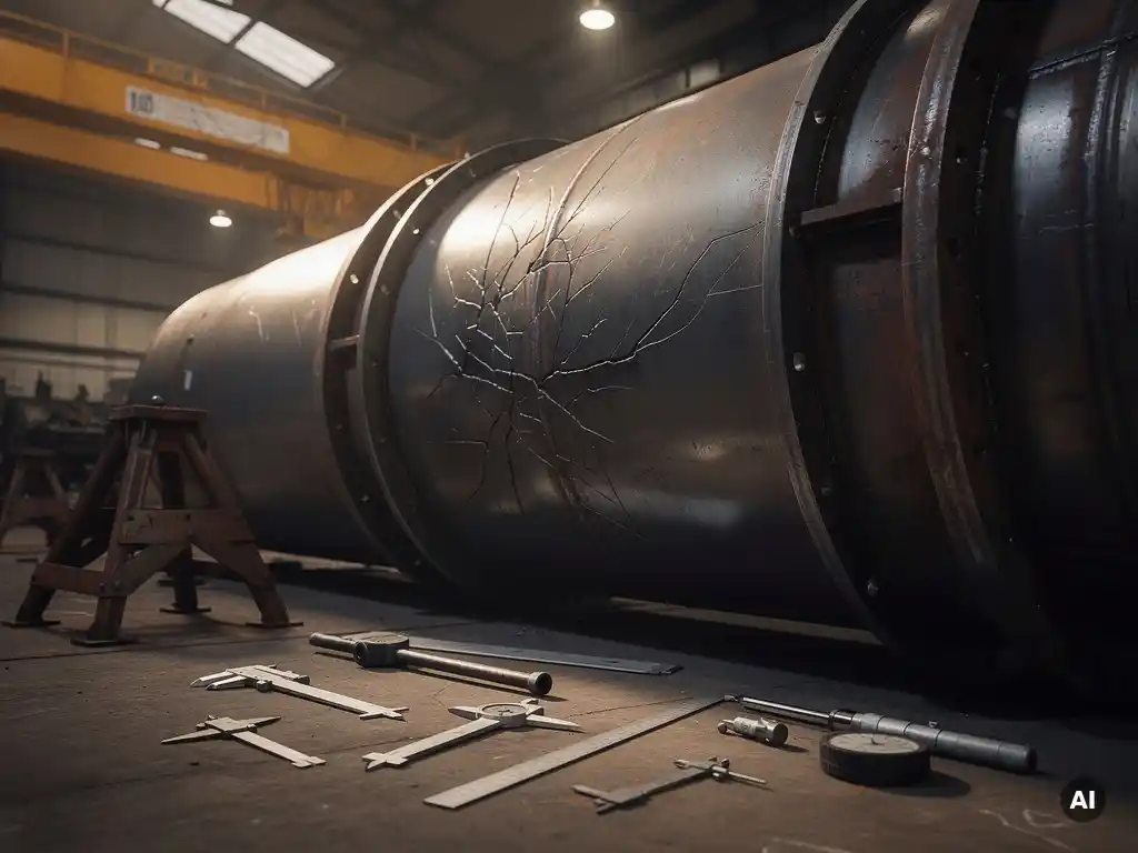
What happens to a pressure vessel’s metal under repeated pressure cycles?
Each time a pressure vessel is pressurised and depressurised, the shell wall expands and contracts. This repeated elastic deformation (even at stress levels far below the material’s ultimate tensile strength) causes progressive microstructural damage known as fatigue. Over enough cycles, microscopic cracks nucleate at stress concentrations such as nozzle welds, support attachments, or geometric discontinuities, and then slowly propagate through the wall thickness.
The critical point is that fatigue damage is cumulative and largely irreversible. Unlike a single overload event, no individual cycle may appear dangerous in isolation. The vessel simply accumulates damage incrementally until a crack reaches a critical size, at which point fracture or leak-before-break behaviour becomes a real risk. This is why pressure cycling is treated as a distinct design and inspection concern, separate from static pressure rating.
Temperature swings that accompany pressure changes add another layer of stress. Thermal gradients create differential expansion across wall sections and between base metal and weld zones, accelerating the fatigue process. Vessels that cycle both in pressure and temperature simultaneously tend to exhaust their fatigue allowance faster than those cycling in pressure alone.
How is design life calculated for pressure vessels under cyclic loading?
Design life under cyclic loading is calculated using fatigue analysis, which relates the number of allowable load cycles to the stress amplitude experienced at critical locations in the vessel. The governing codes, including ASME Section VIII Division 2, EN 13445, and AD Merkblätter, each provide fatigue curves (S-N curves) that define how many cycles a given material can sustain at a given stress range before failure probability becomes unacceptable.
The calculation process follows a defined sequence:
- Identify all loading events: pressurisation, depressurisation, temperature changes, hydraulic test cycles, and any operational transients that create stress variation.
- Determine stress ranges at critical locations, typically using detailed stress analysis or finite element analysis (FEA) at nozzles, welds, and thickness transitions.
- Apply the relevant fatigue curve for the material and weld class to obtain the allowable number of cycles at each stress amplitude.
- Accumulate damage using Miner’s rule: each cycle type consumes a fraction of total life, and the sum of all fractions must remain below 1.0 for the vessel to meet its design life.
- Apply safety factors as required by the applicable code, accounting for surface finish, weld quality, and environmental effects.
In-house fatigue analysis capability matters considerably here. Coek Engineering’s design team performs supplementary fatigue analysis and FEA as standard options alongside code calculations, ensuring that vessels intended for cyclic service are properly assessed rather than simply rated for static pressure.
What design features reduce fatigue damage in cyclic pressure service?
Several fabrication and geometric choices have a direct impact on how quickly fatigue damage accumulates in a pressure vessel. The underlying principle is straightforward: stress concentrations are where cracks initiate, so eliminating or reducing them extends cycle life significantly.
The most effective design features include:
- Full-penetration welds with smooth profiles: weld toes are primary crack initiation sites; flush-ground or post-weld treated welds substantially reduce local stress peaks.
- Generous transition radii at nozzle connections, shell-to-head junctions, and thickness changes: abrupt geometry changes amplify stress; smooth transitions distribute it.
- Reinforced nozzle designs: set-in nozzles with generous fillet radii or forged integral nozzles outperform simple set-on constructions in cyclic service.
- Controlled weld residual stresses: post-weld heat treatment (PWHT) reduces tensile residual stresses that would otherwise add directly to cyclic stress amplitudes.
- Minimised internal attachments at high-stress zones: internal clips, baffles, and support rings welded into high-stress areas create local stress raisers that can be repositioned during design.
- Thick-wall construction where warranted: heavier walls reduce membrane stress amplitude per cycle, directly extending fatigue life at the cost of increased weight.
The quality of fabrication execution is as important as the design intent. Weld geometry, surface condition, and dimensional accuracy all influence where fatigue cracks actually initiate in service, which is why fabrication quality standards are not interchangeable between static and cyclic-service vessels.
How does material selection affect fatigue life in pressure cycling applications?
Material selection affects fatigue life through several mechanisms: inherent fatigue strength, sensitivity to surface condition and weld quality, corrosion resistance, and fracture toughness once a crack has initiated. For cyclic-service pressure vessels, material choice is not simply about tensile strength: a higher-strength alloy does not automatically deliver longer fatigue life, particularly in welded construction.
In welded pressure equipment, the fatigue performance of weld zones often governs overall life more than the base metal properties. Weld defects, geometric discontinuities, and heat-affected zone microstructure can reduce effective fatigue strength significantly regardless of the base material’s nominal rating. This is why weld procedure qualification, non-destructive examination, and post-weld treatment matter as much as the material specification itself.
For applications combining cyclic loading with corrosive media, material selection becomes even more critical. Titanium, zirconium, and high-nickel alloys such as Hastelloy and Inconel maintain their fatigue resistance in aggressive chemical environments where carbon steel or standard stainless grades would suffer accelerated corrosion fatigue, a mechanism discussed in the next section. Clad construction, using a carbon steel structural shell with a corrosion-resistant inner layer, is a practical approach that preserves mechanical fatigue performance while providing the necessary chemical resistance at lower cost than solid exotic alloys.
What’s the difference between pressure cycling fatigue and corrosion fatigue?
Pressure cycling fatigue is driven purely by mechanical stress variation: the metal cracks because repeated elastic strain accumulates damage over time, independent of the chemical environment. Corrosion fatigue is a combined mechanism where an aggressive environment and cyclic stress act simultaneously, accelerating crack initiation and propagation well beyond what either factor would produce alone.
The practical consequences of this distinction are significant. In pure mechanical fatigue, a material has a defined endurance limit below which cycles can theoretically be sustained indefinitely. In corrosion fatigue, that endurance limit effectively disappears: even low stress amplitudes will eventually cause cracking if the environment is sufficiently aggressive. This means that a vessel correctly designed for its mechanical cycle count may still fail prematurely if the process fluid is corrosive and material selection did not account for the combined effect.
Corrosion fatigue is particularly relevant in vessels handling halide-containing media, acidic process streams, or alternating wet and dry conditions. Crack propagation rates in corrosion fatigue can be orders of magnitude faster than in inert environments. Protective measures include selecting inherently corrosion-resistant materials for wetted surfaces, applying appropriate coatings or cladding, minimising crevices where aggressive media can concentrate, and ensuring that inspection intervals are set conservatively to detect corrosion fatigue cracks before they reach critical size.
When should a pressure vessel be retired or inspected due to cycle accumulation?
A pressure vessel should be formally assessed for retirement or enhanced inspection when accumulated operating cycles approach a significant fraction of the design fatigue life, typically when the calculated damage fraction reaches 80% of the allowable limit, or when cycle counts exceed what was assumed in the original design basis. The specific threshold depends on the applicable pressure equipment regulations, the operator’s risk management framework, and the consequences of failure.
Cycle accumulation should be actively tracked throughout vessel life, not reconstructed retrospectively. Operators who lose track of actual cycle counts, particularly after plant modifications, process upsets, or changes in operating mode, face uncertainty that typically results in conservative early retirement or costly fitness-for-service assessments.
Inspection decisions linked to cycle accumulation should focus on the locations identified as highest-risk during the original fatigue analysis: nozzle welds, shell-to-head transitions, and any geometric discontinuities. Relevant inspection techniques include magnetic particle testing, dye penetrant testing, and phased-array ultrasonic testing, selected based on the location, material, and crack orientation expected from the fatigue mechanism.
Where a vessel has exceeded its original design cycle count but shows no detectable cracking, a formal fitness-for-service evaluation under standards such as API 579 or BS 7910 can establish whether continued operation is justifiable, and if so, under what inspection interval and operating constraints. Retirement is not always the immediate conclusion, but it must be an engineering decision, not a default.
How Coek Engineering supports pressure vessel design for cyclic service
Designing and fabricating pressure equipment for cyclic service requires more than meeting a static pressure rating. At Coek Engineering, technically demanding vessels, including those subject to pressure cycling, temperature transients, or combined corrosion and fatigue conditions, are approached with the full depth of in-house mechanical engineering and fabrication expertise that these applications demand.
Coek’s capabilities relevant to cyclic-service pressure equipment include:
- Fatigue analysis and FEA performed in-house alongside standard code calculations (ASME, EN 13445, AD Merkblätter)
- Advanced materials expertise covering titanium, zirconium, Hastelloy, Inconel, and other alloys suited to combined cyclic and corrosive service
- More than 30 years of clad construction experience, combining structural carbon steel with corrosion-resistant inner layers for cost-effective fatigue and corrosion performance
- Precision fabrication of thick-walled, large-scale, and geometrically complex vessels where weld quality and dimensional accuracy directly affect fatigue life
- Compliance with international standards including ISO 9001, PED, and ASME certifications
If your project involves pressure equipment for cyclic or otherwise technically demanding service conditions, contact Coek Engineering to discuss your requirements with our engineering team.
Frequently Asked Questions
How many pressure cycles does it typically take before fatigue damage becomes a serious concern?
There is no universal threshold — it depends on the stress amplitude at critical locations relative to the material’s fatigue curve. A vessel experiencing high stress ranges at nozzle welds may exhaust its fatigue allowance in as few as a few thousand cycles, while a well-designed vessel operating at low stress amplitudes may tolerate hundreds of thousands of cycles. This is precisely why a formal fatigue analysis, rather than a rule-of-thumb cycle count, is the only reliable way to establish when a specific vessel enters a danger zone.
What are the most common mistakes engineers make when designing pressure vessels for cyclic service?
The most frequent mistake is treating a cyclic-service vessel as if it were a static-pressure vessel — sizing it to the rated pressure without performing a dedicated fatigue analysis. A closely related error is underestimating the number or severity of loading events, particularly hydraulic test cycles, start-up and shutdown transients, and process upsets, which are often omitted from the design cycle count. A third common oversight is specifying weld quality and inspection requirements appropriate for static service, when cyclic service demands stricter weld profile control, post-weld heat treatment, and more thorough non-destructive examination.
Can an existing pressure vessel be retrofitted or modified to extend its fatigue life?
Yes, in some cases fatigue life can be extended through engineering interventions, though the options depend on the vessel’s current condition and remaining damage fraction. Weld toe grinding, shot peening, or high-frequency mechanical impact (HFMI) treatment can reduce local stress concentrations at critical weld locations and meaningfully extend remaining life. Operating modifications — such as reducing cycle frequency, limiting pressure swing amplitude, or controlling ramp rates — reduce the stress range per cycle and slow further damage accumulation. Any such intervention should be backed by a revised fatigue assessment and, ideally, a fitness-for-service evaluation under API 579 or BS 7910 before returning the vessel to service.
How does hydraulic pressure testing affect a vessel's fatigue life budget?
Hydraulic tests are full-pressure loading events and do consume a portion of the vessel’s fatigue life, even though they are performed at controlled conditions. Most design codes account for a defined number of hydrotests within the original fatigue calculation, but vessels that are retested multiple times over their service life — for example, after repairs or regulatory re-certification — can accumulate test-related fatigue damage beyond what was assumed at design. Operators should ensure that each hydrotest event is logged and included in the cumulative damage fraction, particularly for vessels already approaching their design cycle limit.
Is finite element analysis (FEA) always necessary for cyclic-service pressure vessel design, or can code calculations alone be sufficient?
Code calculations using simplified stress analysis methods are sufficient for many standard geometries and moderate cycle counts, and most design codes provide screening criteria to determine whether a detailed fatigue analysis is required at all. However, FEA becomes essential when the vessel has complex geometry, non-standard nozzle configurations, or localized stress concentrations that simplified methods cannot accurately capture. For vessels with high cycle counts, aggressive operating conditions, or consequences of failure that justify conservative design, FEA provides the accuracy needed to optimize the design without over-engineering it — making it a worthwhile investment rather than an optional extra.
How should operators track pressure cycles in service, and what records should be maintained?
Cycle tracking should be built into the plant’s operational monitoring system from commissioning, not added retrospectively. At minimum, records should log each pressurization and depressurization event, the associated pressure range, any significant temperature excursions, and any off-normal transients such as pressure surges or emergency shutdowns. Modern process control systems can automate this logging, but even a simple manual log is far better than relying on memory or design assumptions. These records feed directly into fitness-for-service assessments and inspection interval decisions, and their absence is one of the most common reasons vessels are retired earlier than their actual fatigue condition would require.
At what point should an operator bring in a specialist engineer rather than relying on the original design documentation?
Specialist review is warranted in several situations: when accumulated cycles are approaching or have exceeded the original design basis, when the operating conditions have changed since the vessel was commissioned (different pressure range, process fluid, or temperature profile), when inspection reveals any cracking or crack-like indications, or when the vessel has undergone repairs that may have altered its fatigue characteristics. Original design documentation captures the vessel as-designed under assumed conditions — a specialist fitness-for-service assessment under API 579 or BS 7910 evaluates the vessel as it actually exists today, which is a meaningfully different question.