
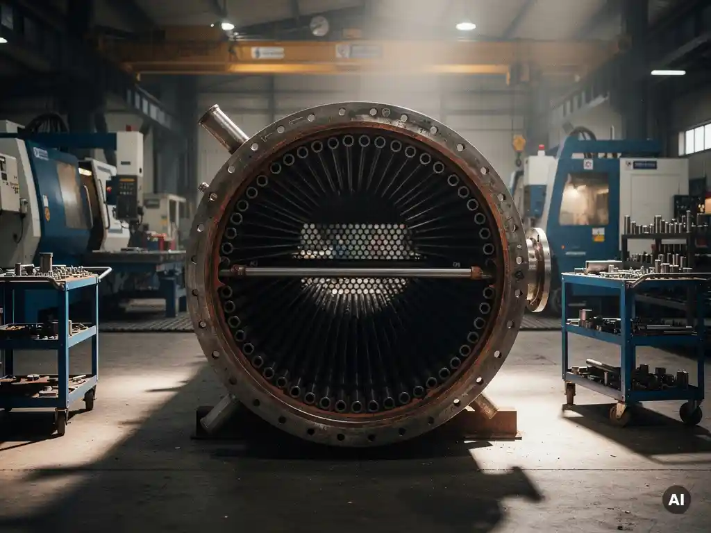
The choice between a fixed tube sheet, U-tube and floating head shell-and-tube heat exchanger depends primarily on thermal expansion, the need for mechanical cleaning access and the corrosivity of the process fluids involved. Fixed tube sheet designs suit low differential thermal expansion and clean tube-side fluids. U-tube and floating head designs address situations where thermal movement, fouling or maintenance access demand greater flexibility. The sections below work through each design in detail, covering when to use each one and how material and maintenance considerations shape the final decision.
What are the main differences between fixed tube sheet, U-tube and floating head designs?
The three main shell-and-tube heat exchanger configurations differ in how the tube bundle is supported, how thermal expansion is managed and how accessible the internals are for cleaning and inspection. Each design represents a different trade-off between mechanical simplicity, thermal flexibility and maintenance practicality.
In a fixed tube sheet design, both tube sheets are welded directly to the shell. The bundle cannot be removed, and any differential thermal expansion between the shell and the tubes must be absorbed by the tubes themselves or by an expansion bellows on the shell. This makes the design compact and cost-effective but limits its applicability when large temperature differentials are present.
A U-tube design uses a single tube sheet. Tubes are bent into a U-shape and return to the same end, allowing the bundle to expand freely. Because there is no second tube sheet, the shell side is straightforward to clean, but the tube-side inner surfaces of the U-bends are not mechanically cleanable.
A floating head design has one fixed tube sheet and one tube sheet that is free to move axially inside the shell. This allows unrestricted thermal expansion while keeping the bundle removable for full mechanical cleaning on both the shell side and the tube side. It is the most mechanically complex and costly of the three configurations.
When should you choose a fixed tube sheet heat exchanger?
A fixed tube sheet heat exchanger is the right choice when the temperature difference between the shell-side and tube-side fluids is small, the tube-side fluid is clean enough to allow chemical cleaning, and minimising equipment cost and footprint is a priority.
Because the tube sheets are permanently welded to the shell, there are no additional gasketed joints or internal floating components. This reduces the number of potential leak paths and simplifies fabrication. For services with modest thermal cycling and non-fouling tube-side fluids, the fixed tube sheet design offers reliable long-term performance at lower initial cost.
The main limitation is differential thermal expansion. When the shell and tubes operate at significantly different temperatures, the fixed connection forces stresses into both the tubes and the shell. Where this is a concern, an expansion bellows can be added to the shell, though this introduces a pressure-containing component that requires its own inspection and maintenance attention.
Fixed tube sheet exchangers are commonly chosen for cooling water services, condensers with moderate temperature ranges and applications where the tube-side fluid is compatible with chemical cleaning methods.
When does a U-tube design make more sense than the alternatives?
A U-tube shell-and-tube heat exchanger is the preferred choice when thermal expansion is a significant concern, the tube-side fluid is relatively clean, and cost efficiency is important. Because the bundle can expand and contract freely, no expansion bellows or floating internals are required.
The single tube sheet construction also means fewer components and a lower fabrication cost compared to a floating head design. The removable bundle allows shell-side cleaning by mechanical means, which is valuable when the shell-side fluid is prone to fouling or scaling.
The trade-off is on the tube side. The inner radius of each U-bend cannot be reached with a straight mechanical cleaning rod. This makes U-tube designs less suitable when the tube-side fluid is fouling, viscous or carries particulate matter that deposits on internal surfaces.
U-tube exchangers are a practical solution for high-pressure, high-temperature services such as feed-effluent exchangers, reboilers and applications where the tube-side fluid is a clean process gas or steam. They are also well suited to services using expensive alloy tube materials, since the single tube sheet reduces material costs compared to a fixed or floating head configuration.
What makes a floating head heat exchanger the right choice?
A floating head shell-and-tube heat exchanger is the right choice when both thermal expansion and full mechanical cleaning access are required simultaneously. It is the most versatile of the three configurations and is typically selected for demanding refinery and chemical process services where fouling on both the shell side and the tube side is a realistic operating concern.
The removable bundle allows the tube side to be cleaned with mechanical tools, including straight rods and brushes, which is not possible with U-tube designs. At the same time, the floating tube sheet accommodates differential thermal movement without imposing stress on the tubes or the shell.
The additional mechanical complexity comes at a cost. Floating head designs involve more components, more gasketed joints and higher fabrication effort. The internal floating head cover, in particular, must be carefully designed and maintained to prevent leakage between the shell-side and tube-side fluids. For services where process fluid mixing would be hazardous, the integrity of this joint is critical.
Despite the higher cost, floating head exchangers are frequently specified for crude oil preheat trains, heavy hydrocarbon services and other applications where predictable fouling behaviour makes regular bundle removal and mechanical cleaning a routine part of operations.
How do material and corrosion requirements influence the choice of design?
Material requirements can significantly influence which shell-and-tube heat exchanger configuration is practical. When corrosive process fluids demand exotic alloy tubes, the number of tube sheets and the complexity of the bundle construction directly affect both material cost and fabrication risk.
Several factors are worth considering:
- Tube sheet material: In corrosive services, tube sheets may need to be solid exotic alloy or clad with a corrosion-resistant layer. A U-tube design requires only one tube sheet, which reduces material cost when the alloy is expensive.
- Shell-side corrosion: If the shell-side fluid is also corrosive, the shell itself may need to be clad or manufactured in a resistant alloy, regardless of the bundle type chosen.
- Galvanic compatibility: When dissimilar metals are used for tubes and tube sheets, galvanic corrosion at the tube-to-tube-sheet joint must be evaluated carefully during design.
- Weld integrity in exotic alloys: Materials such as titanium, zirconium and Hastelloy require specialist welding procedures. The more tube-to-tube-sheet welds a configuration requires, the more critical fabrication quality becomes.
- Clad construction: For large exchangers where solid exotic alloy would be prohibitively expensive, explosion-clad shells and tube sheets offer a cost-effective alternative that combines structural carbon steel with a corrosion-resistant bonded layer.
In highly corrosive applications, the choice of design type is often constrained by what can be reliably fabricated in the required material. A floating head design in solid zirconium, for example, is far more complex to manufacture than a fixed tube sheet exchanger in the same material, and the additional joints introduce more potential failure points in an already demanding environment.
How does maintenance access affect long-term operating cost?
Maintenance access is one of the most consequential factors in the total cost of ownership of a shell-and-tube heat exchanger. A design that is cheaper to purchase but difficult to clean or inspect can result in significantly higher operating costs over its service life.
The key maintenance considerations for each design type are:
- Fixed tube sheet: The bundle cannot be removed. Tube-side cleaning relies on chemical methods or high-pressure water jetting through the nozzles. Shell-side cleaning is not mechanically possible without cutting the shell open. This design has low maintenance costs when fouling is minimal but is expensive when it is not.
- U-tube: The bundle is removable, allowing full shell-side mechanical cleaning. Tube-side cleaning is limited to the straight sections of the tubes. It is acceptable for moderate fouling on the tube side, but not suitable for heavy or particulate fouling.
- Floating head: The bundle is fully removable and both shell-side and tube-side surfaces are accessible for mechanical cleaning. This is the highest-maintenance-access configuration and the most appropriate for services with predictable fouling on both sides.
Process engineers and equipment engineers should assess the expected fouling rates on both sides of the exchanger and factor in the frequency and cost of planned cleaning outages. In some cases, specifying a floating head design with higher upfront cost results in lower total lifecycle cost when cleaning intervals are short or when unplanned fouling-related shutdowns carry significant production penalties.
How Coek Engineering approaches shell-and-tube heat exchanger design
Coek Engineering manufactures custom shell-and-tube heat exchangers for technically demanding industrial applications where standard configurations and commodity fabrication are insufficient. The focus is specifically on exchangers that involve challenging combinations of pressure, temperature, corrosive media and advanced materials.
Relevant capabilities include:
- Design and fabrication in exotic alloys including titanium grades, zirconium, tantalum and Hastelloy
- Clad tube sheet and shell construction combining structural carbon steel with corrosion-resistant bonded layers
- In-house mechanical engineering aligned with ASME, TEMA, AD Merkblätter and HTRI standards
- Supplementary analysis including FEA, fatigue, thermal and vibration analysis performed by in-house specialists
- Experience across demanding process environments including PTA, acetic acid, brine purification, biofuels and MEG applications
If you are specifying a shell-and-tube heat exchanger for a corrosive, high-pressure or thermally demanding service and need a fabrication partner with the materials expertise and engineering depth to match, contact Coek Engineering to discuss your project requirements.
Frequently Asked Questions
Can I retrofit a fixed tube sheet exchanger with an expansion bellows if thermal stress becomes a problem after commissioning?
Yes, it is technically possible to add an expansion bellows to an existing fixed tube sheet exchanger, but it is not a straightforward modification. The shell must be cut, the bellows assembly welded in, and the entire pressure-containing envelope re-inspected and re-certified to the applicable code (ASME, AD Merkblätter, etc.). It is far more cost-effective to anticipate differential thermal expansion during the design phase and specify the bellows from the outset, or to reconsider whether a U-tube or floating head design would be more appropriate for the service.
What are the most common mistakes engineers make when selecting between these three designs?
The most frequent mistake is selecting a design based on purchase cost alone without accounting for the full lifecycle cost of cleaning, inspection and unplanned downtime. A fixed tube sheet exchanger may appear attractive on a capital budget, but if the service involves fouling tube-side fluids, the inability to mechanically clean the bundle can lead to costly production losses. A close second is underestimating differential thermal expansion — particularly in services with variable operating conditions — and specifying a fixed tube sheet design without adequate expansion accommodation.
How do I determine whether my tube-side fluid is 'clean enough' for a U-tube or fixed tube sheet design?
The practical test is whether the fluid’s fouling tendency can be managed by chemical cleaning or high-pressure water jetting alone, without requiring mechanical rodding. Review your fluid’s fouling factor (typically expressed as m²·K/W or ft²·°F·hr/BTU per TEMA standards), check whether it carries suspended solids or polymerising compounds, and consult your process licensor or operating data from similar services. If the fouling factor exceeds TEMA guidelines for the service category, or if the fluid is known to deposit hard scale or particulates, a design that allows mechanical tube-side cleaning — i.e., a floating head — is the safer specification.
Are there any process conditions where none of the three standard designs is suitable and a completely different heat exchanger type should be considered?
Yes. When process fluids are extremely viscous, highly fouling on both sides, or when very close temperature approaches are required with low pressure drop, alternatives such as scraped-surface heat exchangers, spiral heat exchangers or plate-and-frame designs may be more appropriate. Similarly, for cryogenic services or highly corrosive duties where even exotic alloy shell-and-tube construction is impractical, brazed aluminium or graphite block heat exchangers are sometimes specified. The shell-and-tube configuration covers a very wide range of industrial duties, but it is not the universal answer for every process condition.
How does the choice of design affect pressure drop and thermal performance?
The bundle configuration directly influences both shell-side and tube-side pressure drop. U-tube designs introduce additional pressure drop in the tube side due to the 180° bend at the return end, which must be accounted for in hydraulic calculations — particularly in high-viscosity or high-velocity services. Floating head designs, depending on the internal head type (pull-through bundle vs. split backing ring), may have slightly different shell-side flow patterns near the floating end. These differences are typically captured in rigorous thermal-hydraulic software such as HTRI Xchanger Suite, and should be evaluated at the rating stage rather than assumed to be negligible.
What role does the TEMA mechanical standards class (R, C or B) play in the design selection decision?
TEMA class defines the minimum mechanical construction standards — including tube sheet thickness, baffle spacing, corrosion allowances and nozzle requirements — and is chosen based on the severity of the service. TEMA R applies to the most demanding refinery and petrochemical services, TEMA C to general commercial applications and TEMA B to chemical process services. The design type (fixed tube sheet, U-tube or floating head) and the TEMA class are independent choices, but in practice, floating head designs are most commonly specified to TEMA R for heavy-duty refinery services, while fixed tube sheet and U-tube designs appear across all three classes depending on the application.
How should I approach the inspection and integrity management of a floating head exchanger given the internal gasketed joint?
The internal floating head cover joint is a critical inspection point because a leak there results in cross-contamination between the shell-side and tube-side fluids — which may be hazardous in many process services. A robust integrity management programme should include gasket replacement at every bundle pull, visual inspection of the floating head cover and backing ring for erosion or corrosion, and hydraulic pressure testing of both circuits after reassembly. For services where fluid mixing is particularly hazardous, some operators specify double-gasketed floating head arrangements or select an alternative design type to eliminate the risk entirely.
Related Articles
- How do pressure, temperature and corrosion affect process column material selection?
- How do you size a pressure vessel for a high-pressure application?
- How does wall thickness affect pressure vessel structural integrity?
- What are the main types of industrial autoclaves used in manufacturing?
- How do you verify the integrity of a clad layer in a pressure vessel after fabrication?