
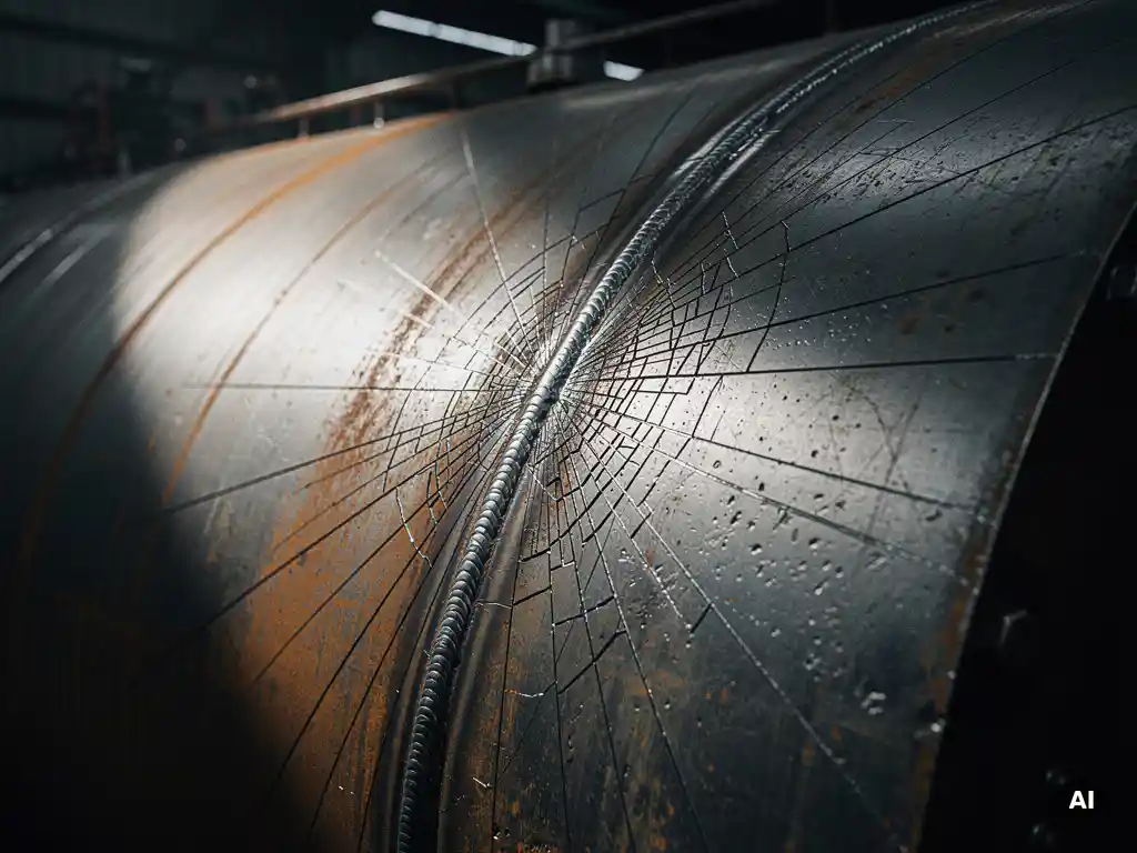
Fatigue cracking in pressure vessels under cyclic loading occurs when repeated stress fluctuations gradually damage the metal at a microscopic level, eventually initiating and propagating cracks that can lead to structural failure. Unlike a single overload event, fatigue failure develops progressively over many loading cycles, often without visible warning until a crack has grown to a critical size. The sections below address the key questions engineers and procurement teams ask when evaluating fatigue risk in pressure equipment.
How does cyclic loading generate fatigue cracks in metal?
Cyclic loading generates fatigue cracks by repeatedly applying and releasing stress in a way that causes localised plastic deformation at the microscopic level. Even when peak stresses remain well below the material’s yield strength, each cycle causes tiny amounts of irreversible slip within the metal’s grain structure. Over thousands or millions of cycles, this accumulated damage nucleates a crack that then grows with each subsequent loading event.
The mechanism follows three distinct stages: crack initiation, stable crack propagation, and final fracture. During initiation, stress concentrations at surface irregularities, inclusions, or geometric discontinuities provide the starting point. Once a crack forms, each loading cycle advances the crack front slightly further into the material. When the remaining cross-section can no longer carry the applied load, sudden fracture occurs. This progression means that fatigue cracking in pressure vessels is rarely an instantaneous event but rather the endpoint of a long, incremental process.
What are the main factors that accelerate fatigue cracking?
The main factors that accelerate fatigue crack propagation in pressure vessels are stress concentration, mean stress level, surface condition, corrosive environment, and loading frequency. Each of these influences either how quickly a crack initiates or how rapidly it advances once formed.
- Stress concentration: Notches, sharp corners, weld toes, and nozzle attachments amplify local stress, dramatically shortening crack initiation life.
- Mean stress: Higher tensile mean stress reduces the number of cycles to failure, even when the stress amplitude remains constant.
- Surface condition: Rough surfaces, corrosion pits, and mechanical damage all act as initiation sites that reduce fatigue resistance.
- Corrosive environment: Exposure to aggressive media accelerates crack growth through corrosion fatigue, where chemical attack and mechanical cycling act together.
- Temperature: Elevated temperatures can reduce material strength and increase creep interaction, compounding fatigue damage.
- Residual stresses: Tensile residual stresses from welding or forming add to applied stresses and accelerate crack growth, while compressive residual stresses have the opposite effect.
Where do fatigue cracks typically initiate in a pressure vessel?
Fatigue cracks in pressure vessels most commonly initiate at geometric discontinuities and weld regions, where stress concentrations are highest. Nozzle connections, manway openings, support attachments, and weld toes are the most frequently observed initiation sites in service experience and post-failure analysis.
Weld toes are particularly vulnerable because they combine three unfavourable conditions simultaneously: geometric stress concentration from the weld profile, potential surface irregularities from the welding process, and tensile residual stresses introduced during fabrication. Internal surfaces exposed to corrosive process media represent another common initiation zone, especially where the protective layer has been compromised or where crevice conditions exist.
Crack initiation at pressure vessel nozzles is especially significant in cyclic service because nozzles introduce both geometric discontinuities and local bending loads. Proper reinforcement design and smooth transition geometry at these locations are therefore critical for fatigue performance.
How does material selection affect fatigue resistance?
Material selection directly affects fatigue resistance through intrinsic properties such as tensile strength, ductility, microstructural cleanliness, and resistance to corrosion fatigue. Higher-strength steels generally show improved fatigue limits in clean laboratory conditions, but this advantage diminishes significantly in corrosive environments or when surface quality is poor.
For pressure vessels operating in aggressive media, corrosion-resistant alloys such as titanium, zirconium, Hastelloy, and Inconel offer superior fatigue performance because they resist the surface degradation that accelerates crack initiation. Clad construction, where a carbon steel shell is lined with a corrosion-resistant inner layer, can provide a practical balance between structural strength and surface protection in demanding cyclic applications.
Material cleanliness also matters. Inclusions and second-phase particles within the metal act as internal stress concentrators that can initiate subsurface fatigue cracks. Selecting materials with tightly controlled chemistry and inclusion ratings is therefore relevant for high-cycle fatigue applications.
What is the difference between high-cycle and low-cycle fatigue in pressure vessels?
High-cycle fatigue involves a large number of loading cycles at stress levels below the material’s yield strength, typically more than 10,000 cycles. Low-cycle fatigue involves fewer cycles at higher stress amplitudes that cause localised plastic deformation with each cycle. The distinction matters because each regime requires a different analytical approach and has different design implications.
In pressure vessel engineering, low-cycle fatigue is the more common concern. Vessels subjected to repeated pressurisation and depressurisation, thermal cycling, or process startups and shutdowns typically accumulate hundreds to a few thousand cycles over their service life rather than millions. These cycles often involve significant stress amplitudes, placing the equipment firmly in the low-cycle fatigue regime where plastic strain accumulation governs crack initiation life.
High-cycle fatigue becomes relevant when pressure vessels are exposed to vibration from attached pipework, pumps, or compressors, or when rapid pressure fluctuations occur in process systems. In these cases, the number of cycles can reach into the millions relatively quickly, and even modest stress concentrations become significant.
How do design codes address fatigue life in pressure vessel engineering?
Design codes address fatigue life in pressure vessel engineering through explicit fatigue analysis procedures that link stress amplitudes, cycle counts, and material fatigue curves to an allowable number of cycles. ASME Section VIII Division 2 and EN 13445 both include fatigue assessment methods that require designers to evaluate the cumulative damage from all anticipated loading conditions over the vessel’s service life.
These codes use design fatigue curves derived from experimental data, incorporating safety factors to account for scatter in material behaviour, surface condition, and environmental effects. The Palmgren-Miner cumulative damage rule is commonly applied when multiple loading conditions with different amplitudes and cycle counts are present, allowing engineers to sum partial damage contributions into a single usage factor.
Where simplified fatigue screening criteria are not satisfied, a detailed fatigue analysis becomes mandatory. This involves calculating stress ranges at all critical locations, identifying the number of cycles for each loading condition, and demonstrating that the cumulative damage ratio remains within code limits. Compliance with these requirements is a fundamental part of the mechanical engineering scope for vessels in cyclic service.
Can fatigue cracking be prevented during fabrication and design?
Fatigue cracking in pressure vessels can be substantially reduced through deliberate design choices and controlled fabrication practices, even though it cannot always be eliminated entirely. The most effective prevention strategies address stress concentration, weld quality, surface condition, and residual stress simultaneously.
- Smooth geometric transitions: Generous fillet radii at nozzle connections, support attachments, and weld details reduce local stress concentration factors significantly.
- Weld quality control: Full-penetration welds, controlled heat input, and post-weld dressing of weld toes reduce both geometric stress concentration and residual stress at critical joints.
- Post-weld heat treatment: Stress relief after welding reduces tensile residual stresses, which are a major driver of fatigue crack growth.
- Surface finish: Smooth internal and external surfaces, free from mechanical damage and corrosion pits, remove ready-made initiation sites.
- Fatigue-aware material selection: Choosing materials appropriate for the operating environment, including corrosion-resistant alloys where needed, prevents the surface degradation that accelerates fatigue.
- Non-destructive examination: Rigorous inspection during and after fabrication detects pre-existing defects before the vessel enters service, preventing accelerated fatigue from existing flaws.
Effective prevention requires that fatigue considerations are built into the design from the outset, not addressed as an afterthought. Vessels designed for cyclic service demand closer collaboration between the process side, which defines the loading conditions, and the mechanical engineering side, which translates those conditions into a vessel that can withstand them reliably over its intended service life.
How Coek supports fatigue-critical pressure vessel projects
For pressure vessels in demanding cyclic service, fabrication quality and engineering rigour are not secondary concerns. Coek Engineering designs and manufactures custom pressure vessels for technically challenging applications where fatigue performance, material selection, and weld integrity are central to the equipment’s reliability.
- In-house mechanical engineering to translate process loading conditions into fatigue-assessed vessel designs
- Advanced materials expertise including titanium, zirconium, Hastelloy, Inconel, and clad constructions suited to corrosive cyclic environments
- Controlled fabrication processes with rigorous weld quality, post-weld heat treatment, and non-destructive examination
- Compliance with ASME, PED, and other international standards relevant to fatigue-critical equipment
- Capability for large, thick-walled, and geometrically complex vessels where standard fabricators may lack the necessary precision
If your project involves cyclic loading conditions, aggressive media, or equipment where fatigue failure would carry serious consequences, contact Coek Engineering to discuss your requirements with our engineering team.
Frequently Asked Questions
How do I know if my pressure vessel needs a formal fatigue analysis or if a simplified screening check is sufficient?
Most design codes, including ASME Section VIII Division 2 and EN 13445, include fatigue screening criteria that allow engineers to bypass a full fatigue analysis if the vessel meets certain conditions — such as a limited number of full-pressure cycles, low stress concentration factors, and non-aggressive operating environments. If your vessel fails any of these screening thresholds, a detailed fatigue analysis becomes mandatory. When in doubt, it is always safer to perform the full assessment, particularly for vessels in cyclic service where the consequences of fatigue failure are severe.
What is corrosion fatigue, and how is it different from standard mechanical fatigue?
Corrosion fatigue occurs when cyclic mechanical loading and chemical attack from an aggressive environment act simultaneously on the metal, producing crack growth rates that are significantly faster than either mechanism alone would cause. Unlike standard mechanical fatigue, corrosion fatigue can eliminate the material’s endurance limit — meaning that even very low stress amplitudes can eventually cause failure if enough cycles accumulate in a corrosive medium. This is why material selection and surface protection are especially critical for pressure vessels handling aggressive process fluids under cyclic conditions.
Can post-weld heat treatment (PWHT) fully eliminate fatigue risk at welded joints?
PWHT significantly reduces tensile residual stresses at welded joints, which is one of the major drivers of fatigue crack initiation and growth, but it does not eliminate fatigue risk entirely. Geometric stress concentration at weld toes and any surface irregularities introduced during welding remain after heat treatment and still contribute to reduced fatigue life. For the best results, PWHT should be combined with weld toe dressing techniques — such as grinding or peening — and rigorous non-destructive examination to address all three contributing factors simultaneously.
How often should a pressure vessel in cyclic service be inspected for fatigue cracking during its operational life?
Inspection intervals for pressure vessels in cyclic service should be determined through a risk-based inspection (RBI) methodology that accounts for the vessel’s design fatigue life, actual cycle count, operating environment, and the consequences of failure. In practice, this typically means more frequent inspections than for static-service equipment, with particular attention to known high-risk locations such as weld toes, nozzle connections, and support attachments. Techniques such as phased array ultrasonic testing (PAUT) and magnetic particle inspection (MPI) are commonly used to detect fatigue cracks at an early, manageable stage before they propagate to a critical size.
Does increasing wall thickness improve fatigue life in a pressure vessel?
Increasing wall thickness reduces the nominal hoop stress for a given operating pressure, which can extend fatigue life in some circumstances — but it is not a reliable standalone solution. Thicker walls can introduce higher welding residual stresses, increase heat input challenges during fabrication, and create steeper stress gradients at geometric discontinuities, all of which can offset the benefit of lower nominal stress. A more effective approach is to address the root causes of fatigue damage — stress concentration, surface condition, and residual stress — through design optimisation and controlled fabrication rather than relying on added thickness alone.
What information does a fabricator need from the process side to properly design a vessel for fatigue service?
To perform a meaningful fatigue assessment, the mechanical engineering team needs a complete loading history from the process side, including the expected number of pressurisation and depressurisation cycles over the vessel’s design life, the range of operating pressures and temperatures, the frequency and magnitude of thermal transients, and any vibration sources such as connected pumps or compressors. It is also important to identify the process fluid’s corrosivity, since this directly affects material selection and fatigue curve applicability. Incomplete or assumed loading data is one of the most common reasons fatigue assessments are either overly conservative or dangerously non-conservative, so early and detailed collaboration between process and mechanical engineering disciplines is essential.
Are there surface treatment methods that can improve the fatigue resistance of an existing pressure vessel?
Yes — several surface treatment methods can improve fatigue resistance, even on vessels already in service. Shot peening and ultrasonic impact treatment (UIT) introduce compressive residual stresses at the surface, counteracting the tensile stresses that drive crack initiation and growth. Weld toe grinding removes the geometric stress concentration at the weld profile and eliminates surface irregularities that act as initiation sites. These techniques are particularly valuable at high-risk locations such as nozzle welds and support attachments, and they are sometimes applied as corrective measures when inspection reveals early-stage fatigue damage before cracking has progressed to a critical depth.
Related Articles
- What is a high pressure autoclave reactor?
- How does nozzle placement affect reactor vessel mechanical performance?
- What are the risks of hydrogen embrittlement in high-pressure reactor vessels?
- What is the difference between a jacketed reactor and a shell-and-tube heat exchanger?
- When does a pressure vessel require thick-wall design?